Always wonderful when you let us know of the state of your art. So I take it that you have the power supply to run out of steam rather than as in AB1 operation with the input be the limiting factor (the grid clamping the signal)? Do you set up your power supply to voltage or current limit? I was thinking of doing a Class AB2 guitar amp yet but did not know if I have the input limit the circuit, the screen or the plate. Sounds like it might be a balancing act with picking the right input and screen voltages against the power supply voltage and transformer impedance.
The power supply can be as fat as you want. I limit the ability to melt the tube by placing some resistance in series with the screen grid. The 50C5 and all of its relatives will have a nearly linear relationship between screen current and power output until you get near clipping, then the screen current goes up very quick. Size the resistor such that the amp can get into the distortion zone without melting the screen grid.
Depending on how your preamp responds, how close it is to distorting, and your personal preferences, you can run the preamp directly from B+, from the tube side of the screen resistor, or a tap anywhere in between the two extremes. This way the preamp can contribute to the distortion profile as it's B+ drops when you hammer the output stage. It also adds to the self limiting factor to prevent blasting the screen grids in the output tubes.
I found the melting point for the screens in these little tubes to be in the 30 to 40 watt range, so we are pretty safe at 20 watts, but it's still best to limit the drive as to not be able to hit 40 watts at hard clip.
Squeezing the most power from any set of tubes requires optimizing their efficiency for the conditions you plan to use. I have three bench power supplies that I can use to put any voltage I want (up to 650 volts) on any element of a tube.
I have a few OPT's of different impedances with multiple secondary taps so that I can directly hit 1250, 2500, 3300, 5000, 6600, and 8000 ohms. I have a load bank that I can use to hit every load from 2 ohms to 16 ohms in half ohm steps. This lets me test tubes with any possible useful load impedance.
I have a pair of my Universal Driver boards mounted on a chunk of wood for a little test station. Those boards can crank out over 100 V RMS of clean drive, with an adjustable DC bias from -150 volts to +100 volts with a very low output impedance via mosfet followers.
This allows me to find the point where the tubes perform their best, or melt them if they don't play nice.
That setup can be seen here extracting 75 WPC from some rather pricey GE 6550's in triode mode.
YouTube
Often one or more choices are fixed up front. If you are using 50 volt series heater tubes, your power supply is likely an isolation transformer. That gives two easy B+ voltages, about 160 to 175 volts (bridge rectifier) and about 320 to 360 volts. Previous testing shows that the little 7 pin tubes like around 3000 to 3500 ohms in P-P on 170 volts and 6000 to 8000 ohms on 330 to 360 volts.
The 4 tube amp with 32ET5's is actually a revised version of the amp I designed for the Hundred Buck Amp Challenge several years ago. After the competition ended and the rules didn't matter I went back and made it into something I liked, not something to fit the rules. It's still ultra low buck using a Triad N-68X ($16) and a Parts Express 300-040 70 volt line transformer for the OPT ($5, now on sale for $3). All 4 tubes are on the dollar list, and the other parts are cheap, so the amp can be built for $50 to $75 depending on chassis and wiring.
The little Parts Express OPT doesn't like much more than 5 watts, and works out to something like 3000 ohms, so running 350 volts isn't possible.
The 50C5 amp on the breadboard needs a 6600 ohm OPT, and all testing is being done with a real guitar amp OPT. It is using a Triad N-68X for power and it doesn't get too hot, but I haven't ran it for an extended period of time. The breadboard does however use a totally new drive scheme that doesn't slam the tubes hard into AB2, in fact the amount of positive grid excursion can be adjusted.
It took a couple minutes for me to find it, but we have been here before. Much of my early testing of these small tubes was done about 2 years ago, and discussed in this thread:
5E3 Blackface Single End Amp
The breadboard seen in post #58 is the exact same one I used to make the breadboard with the 50C5's in it seen earlier in this thread. It is now on its 3rd life, as it has been recycled twice.
In post #73 the need for negative supplies and the added complications it requires. That's OK high dollar HiFi amp, but impractical for an under $100 guitar amp. I mentioned the possibility of using screen drive, or dual drive, but both seemed to be easy ways to blow up tubes and mosfets in cranked to 11 guitar amp applications.
Maybe 10 years ago I set out to find ways around these limitations. The results of that work is beginning to bear fruit. Much of it has been directed at HiFi amp boards.
I am working on the second iteration PCB layout of a board I call UNSET right now, and there is a push pull HiFi amp right behind it that squeezes 50 to 70 WPC out of “9 watt” 6GF5 TV sweep tubes. As always, all my work including schematics will be posted once I’m sure of the design. This stuff is so far away from the norm that I am doing far more than my usual testing, and still fighting a few gremlins.
Depending on how your preamp responds, how close it is to distorting, and your personal preferences, you can run the preamp directly from B+, from the tube side of the screen resistor, or a tap anywhere in between the two extremes. This way the preamp can contribute to the distortion profile as it's B+ drops when you hammer the output stage. It also adds to the self limiting factor to prevent blasting the screen grids in the output tubes.
I found the melting point for the screens in these little tubes to be in the 30 to 40 watt range, so we are pretty safe at 20 watts, but it's still best to limit the drive as to not be able to hit 40 watts at hard clip.
Sounds like it might be a balancing act with picking the right input and screen voltages against the power supply voltage and transformer impedance.
Squeezing the most power from any set of tubes requires optimizing their efficiency for the conditions you plan to use. I have three bench power supplies that I can use to put any voltage I want (up to 650 volts) on any element of a tube.
I have a few OPT's of different impedances with multiple secondary taps so that I can directly hit 1250, 2500, 3300, 5000, 6600, and 8000 ohms. I have a load bank that I can use to hit every load from 2 ohms to 16 ohms in half ohm steps. This lets me test tubes with any possible useful load impedance.
I have a pair of my Universal Driver boards mounted on a chunk of wood for a little test station. Those boards can crank out over 100 V RMS of clean drive, with an adjustable DC bias from -150 volts to +100 volts with a very low output impedance via mosfet followers.
This allows me to find the point where the tubes perform their best, or melt them if they don't play nice.
That setup can be seen here extracting 75 WPC from some rather pricey GE 6550's in triode mode.
YouTube
Often one or more choices are fixed up front. If you are using 50 volt series heater tubes, your power supply is likely an isolation transformer. That gives two easy B+ voltages, about 160 to 175 volts (bridge rectifier) and about 320 to 360 volts. Previous testing shows that the little 7 pin tubes like around 3000 to 3500 ohms in P-P on 170 volts and 6000 to 8000 ohms on 330 to 360 volts.
The 4 tube amp with 32ET5's is actually a revised version of the amp I designed for the Hundred Buck Amp Challenge several years ago. After the competition ended and the rules didn't matter I went back and made it into something I liked, not something to fit the rules. It's still ultra low buck using a Triad N-68X ($16) and a Parts Express 300-040 70 volt line transformer for the OPT ($5, now on sale for $3). All 4 tubes are on the dollar list, and the other parts are cheap, so the amp can be built for $50 to $75 depending on chassis and wiring.
The little Parts Express OPT doesn't like much more than 5 watts, and works out to something like 3000 ohms, so running 350 volts isn't possible.
The 50C5 amp on the breadboard needs a 6600 ohm OPT, and all testing is being done with a real guitar amp OPT. It is using a Triad N-68X for power and it doesn't get too hot, but I haven't ran it for an extended period of time. The breadboard does however use a totally new drive scheme that doesn't slam the tubes hard into AB2, in fact the amount of positive grid excursion can be adjusted.
It took a couple minutes for me to find it, but we have been here before. Much of my early testing of these small tubes was done about 2 years ago, and discussed in this thread:
5E3 Blackface Single End Amp
The breadboard seen in post #58 is the exact same one I used to make the breadboard with the 50C5's in it seen earlier in this thread. It is now on its 3rd life, as it has been recycled twice.
In post #73 the need for negative supplies and the added complications it requires. That's OK high dollar HiFi amp, but impractical for an under $100 guitar amp. I mentioned the possibility of using screen drive, or dual drive, but both seemed to be easy ways to blow up tubes and mosfets in cranked to 11 guitar amp applications.
Maybe 10 years ago I set out to find ways around these limitations. The results of that work is beginning to bear fruit. Much of it has been directed at HiFi amp boards.
I am working on the second iteration PCB layout of a board I call UNSET right now, and there is a push pull HiFi amp right behind it that squeezes 50 to 70 WPC out of “9 watt” 6GF5 TV sweep tubes. As always, all my work including schematics will be posted once I’m sure of the design. This stuff is so far away from the norm that I am doing far more than my usual testing, and still fighting a few gremlins.
I remember that well. I went as far as procuring tubes, power and output transformers, and building a voltage-doubler B+ power supply around a Triad N68x. I bought a smaller, lower-voltage mains transformer to provide bias voltage and to power the drive MOSFETs with. Right after that life hit me with a few challenges, and by the time I'd dealt with those a few months later, I'd found another shiny object to play with. 😱...we have been here before...
One very interesting thing I stumbled across maybe a year ago is this inexpensive affordable Recom dual-rail power supply module: RAC10-15DK/277 Recom Power | Power Supplies - Board Mount | DigiKey...the need for negative supplies and the added complications it requires...
Not only do you get +/- 15V at up to 340 mA for $16 (CAD), but this module can actually be powered by DC as well as AC - and it can handle being powered by up to 430 volts DC, meaning it can be run directly off the B+ rail of an existing 350V DC guitar amp power supply.
Here's the datasheet: https://recom-power.com/pdf/Powerline_AC-DC/RAC10-K_277.pdf
The remaining question is whether +/- 15 volts is enough to power drive MOSFETs for the output tubes. From the 12AB5 datasheet, for instance, it looks as though +15V to the control grid may be all that's needed to get deep into AB2, so +15V to the drive MOSFET drains might be enough. But -15V would be marginal for the DC bias for some tubes, and would leave the drive MOSFETs cut off on negative signal swings.
It would be really nice if someone started making a similar module that spits out more voltage, especially on the negative rail, but for now, I can't find anything like that at Digikey. I suppose one could use two separate modules, one for the positive and one for the negative MOSFET power rail, but that starts to feel like a string and duct-tape solution.
-Gnobuddy
I guess I've been looking in the wrong place. Still thinking about ways to power driver MOSFETs, which in turn drive the output tubes into AB2, I just saw this on Alibaba ("DC-DC Boost Converter 8V-32V to +/-45V-390V Adjustable"): High Voltage DC DC Boost Converter 8V 32V to +/ 45V 390V Adjustable ZVS Capacitor Charging Power Supply Module|Replacement Parts & Accessories| - AliExpress
This module needs to be fed low-voltage DC, so it won't run straight off a 350V DC B+ rail, and is not as elegant a solution as the Recom module in my previous post. But it could be fed from, say, a 12V DC SMPS that also powers all the heaters. That wouldn't work for 32ET5s or 50C5s, but the 50C5's lower-voltage cousin - 12C5 - would work.
I think I also have a few 17C5, and I could see a pair of those being powered off an old 19V laptop PSU (with a small series dropping resistor). Three 6N2P heaters in series will also run on 19V, and six triodes is plenty for all the preamp and phase-splitter duties.
On the plus side, the output of this Alibaba module can be adjusted between +/- 45 V to +/- 390V, so it can provide relatively low-voltage rails for driver MOSFETs in guitar amps, or higher voltage MOSFET power rails for tube Hi-Fi, where MOSFET reverse transfer capacitance modulation might be a concern.
-Gnobuddy
The power supply can be as fat as you want. I limit the ability to melt the tube by placing some resistance in series with the screen grid.
Which got my happy feet going. Even more with the rest of your post, just no reason to replete it. I do remember bits and pieces that you have let us know over the years, but with them being in different threads and different times things get lost in the old memory.
I like Gnobuddy has had challenges but think I may have time to play around with AB2 this summer or if not this winter. Unlike GB I have known about the switching boards he linked two, I think I have a couple but at least one. I thought I mentioned them, they were in my plans for a AB2 amp. When we get a thread going we will have to past your posts into it.
I remember that you and I both have an older "ZVS Capacitor charging 390V boost" module that produces a single positive high voltage....switching boards...were in my plans for a AB2 amp.
But I think this one is new - it seems to provide both positive and negative high voltage rails simultaneously. At first sight, at least, that looks perfect for powering Tubelab-like driver MOSFETs. Rails are adjustable from +/- 45V to +/- 390V.
For a guitar amp, I assume we also have to limit positive signal swings to the control grids to avoid control grid failure. The 12AB5 (one of the few datasheets I can find with positive grid voltages on it) shows curves with up to +15V on the control grid. If fixed-biased at, say, -25V, then the control grids can swing from -25V up to +15V, a 40-volt swing. Do we need to also provide symmetrical negative swings (going down to -65V)? Or, since the tube is cut off beyond about -30 V, is that the maximum negative signal needed?
So perhaps what we want is something like a +18V, -36V supply for the MOSFETs? Maybe that would be easiest to get from a traditional 60 Hz 12.6V transformer, with a doubler for the negative rail, and a half-wave rectifier for the positive rail. I think I went through similar reasoning a couple of years ago, and bought a 12-0-12 (or 12.6 - 0 - 12.6) transformer for this job, before abandoning the project and eventually forgetting all about it. 😱
I feel as though I haven't yet fully wrapped my brain around the MOSFET drive, fixed-bias, AB2 layout. The basic idea is simple and clear enough, but there are still some details that aren't clear in my head.
For instance: considering the large input capacitance of MOSFETs, how big does the input coupling capacitor need to be to avoid creating a voltage-divider with the MOSFET input capacitance? And if we use this large coupling capacitor, will the resulting -3dB frequency be too low to be good for a guitar amp? And if we fix this by reducing the MOSFET gate bias resistor, how will we then get enough drive current out of the preceding tube phase-splitter stage?
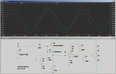
Anyway, first things first. Does the attached LTSpice sim look about right? (Only one half of the PP output is shown, and no output transformer to keep things simple, just a tiny anode resistor to help me plot the anode current.)
In the plot, the green trace = input signal to MOSFET; blue trace = signal on control grids of output tubes; red trace = anode current.
I used the Dirk Reefman model for the 6V6GT, and whatever reasonable-looking MOSFET and 12V zener diode I found in LTSpice. Mr. Reefman is from Europe, and unsurprisingly, I found no included models for 32ET5 or 50C5, though perhaps they exist somewhere on the 'Net.
Supposedly the Reefman LTSpice vacuum tube models are pretty good, but I have made no attempt to verify the accuracy of the 6V6GT model. I'm not really looking for an accurate model here, but rather something I can play with to get the concepts clear in my head.
-Gnobuddy
Attachments
It just dawned on me again (been there before, forgot) that the driver MOSFETs are in source-follower mode, so there's no Miller effect, and the input capacitance will be much smaller.
And IIRC some of George's data (15 V signals through a 1k control grid resistor) suggests no more than 1 mA control grid current at Vgk=+15V, which means a really small MOSFET would do the job - maybe even an LND150, which has very low input capacitance for a MOSFET.
-Gnobuddy
And IIRC some of George's data (15 V signals through a 1k control grid resistor) suggests no more than 1 mA control grid current at Vgk=+15V, which means a really small MOSFET would do the job - maybe even an LND150, which has very low input capacitance for a MOSFET.
-Gnobuddy
- Home
- Live Sound
- Instruments and Amps
- 50c5 push-pull for guitar?