1/ Measure the voltage on each side of R316. We are measuring from ground now. Should be around +44 volts on each side.
43V on PS side, 42,5V on power amp side
2/ Measure the voltage on R320. Should be -44v each side.
-42,5V on each side
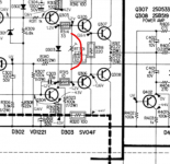
3/ D301 and D302 are types I don't recognise, however D302 looks like it will be a double diode (two series diodes).
Compare channels but I think you should find around 1.2 volts across D302 (so not from ground now).
D302
L-CH 1.2V
R-CH 0.003V
4/ D301 is a Zener and used to generate a stable voltage to connect R309 so it bias the upper transistors with a clean supply.
Just compare the voltage on D301 with the good channel. Reading from ground you should see +44v on the top end (stripy end if they have a stripe) and something like 30 volts on the other end. It all depends on the Zener voltage which will subtract from the +44v.
D301
L-CH 41.7V / 30.4V
R-CH 42.5V / 31V
Just make sure both are similar.
D302 is looking super suspicious with no voltage across it. Even a shorted transistor that it supplies would still leave... quick calculation... 12 v Zener, 12v across R309 (we will discount the 470 ohms as they are low value and wont influence the calculation much... so that gives 12/6800 which is 1.8 milliamps.
1.8 milliamps in 470 ohm (assuming worst case that Q302 was short circuit B to E) would develop 0.84 volts across D302.
Do a resistance check across D302 just to see if it reads really low but what if the 6k8 was open 😉
So we need to check that as well, out of circuit.
1.8 milliamps in 470 ohm (assuming worst case that Q302 was short circuit B to E) would develop 0.84 volts across D302.
Do a resistance check across D302 just to see if it reads really low but what if the 6k8 was open 😉
So we need to check that as well, out of circuit.
If you find anything, don't switch on without first setting the bias preset to minimum resistance... and tbh I would still advise a bulb tester.
The diode can be checked in circuit because we are really looking for a low resistance and that kind of fault would always show.
Resistor with one leg isolated.
Resistor with one leg isolated.
The diode can be checked in circuit because we are really looking for a low resistance and that kind of fault would always show.
Resistor with one leg isolated.
Diode reads 2Ohms in both directions (in circuit)
Time to take it out and check it. It's zonked though with a reading like that.
Two 1N4148's in series should be OK as a replacement.
Two 1N4148's in series should be OK as a replacement.
D302 (actually D352, right CH), read OL in one direction and very low voltage (0.003V) in the other direction on the diode test setting on my DMM.
I put in a new one (two 1N4148's in series). I did not yet make my bulb tester. do you think I should have a go at switching it on – bias down to lowest resistance?
I put in a new one (two 1N4148's in series). I did not yet make my bulb tester. do you think I should have a go at switching it on – bias down to lowest resistance?
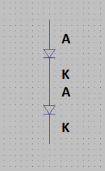
They connect like this. K or cathode is the end with a stripe.
yes, did it that way. And I've inserted them in the direction of the single diode marked on the board. they measured good after soldering 🙂
It is up to you if you want to risk it... its 100% your choice.
All I can say is that the amp has been OK up to now with full rail voltage and so provided the bias preset is at zero ohms that should remain the case.
In fact I'm going to say that if you want to do this then you should link the preset out with wire. That would safeguard the outputs in the event more current than the preset could handle flowed and the preset failed. Unlikely scenario but better to have it covered.
Tying the base of the drivers together prevents any voltage developing that could cause the outputs to conduct heavily and fail.
You could even short the diode D303 out as that would achieve the same thing.
This is making me hungry, the suspense is to much 😀
Assuming it doesn't release magic smoke from anywhere you then check the DC offset is still zero and if it is then you can try a speaker.
Attachments
Great. I'll try by linking out the pot. I'll do this later as I have a video conference coming in... enjoy your meal! I'll report back.

IT WORKS!
awesome. both channels good. no audible distortion. tested with headphones, to late to assemble all and relocate the amp to the speakers.
THAT'S TRULY FANTASTIC. SO MANY THANKS FOR WALKING ME THROUGH THIS. I'D NEVER HAVE MADE IT ALONE. AND I LEARNED SO MUCH.
I have shorted the preset pot as you suggested. what is the exit strategy now? risk to unsolder the short and dial in the right bias?
the pot per se actually makes a good impression, it's not one of those flimsy cardboard ones you see on some amps of this vintage.
I'll also need to replace the D302 in the other channel with two new ones in series, as that's still a "death diode" there.
good night! thanks again. need to walk the dog now... the cat will stalk us and then walk with us.
Wow 😀 You sound surprised 😉
Firstly... and remember this 🙂 that it all works in its present state at this moment and the one thing we do not want to do is cause a problem that might cause damage to the output stage and that is easily done if any little thing goes amiss. You have no safety net of a bulb tester.
If you replace diode D302 in the other channel then you must first begin by turning the bias right down on that channel as well. The change in diode voltage, even though small will either increase or decrease the bias from where it is now.
What are we (you) doing about D303. Are you replacing them with that mod or leaving them or...
Thanks. Well, in the midst of it I wasn't sure if I would arrive at the other shore... of the ocean 🙂
Yes, I'll remember. This is why I did not touch anything else. And thanks for the advice re D302, I wouldn't have thought of readjusting the bias. another possible disaster spotted 🙂
As the amp will go to a family member who has no practice in troubleshooting and repairing (or asking for help in this forum 🙂 and he'll keep it probably for years as the only device to get music out of, everything should be done in a way one can assume that it will work for a long time.
Obviously these diodes are failure-prone, so I should replace them... although I am already afraid of mixing up B and C or E when soldering.
When I opened the amp for the first time after it had stopped working (actually a couple of years after it had) I found that D353 had unglued from its seat right at one of the screws of an output transistor. They are glued – or fixed with resin – into a metal bracket wich is fixed to the transistor screw with a lug. I glued D353 back – but that might not last long.
So, yeah, I gave the answer. Need to put in the SONY mod.
I am wondering if I should simply prioritize assembling the DBT NOW... would be the right occasion, and I'll need it anyhow. Will take some days, though, as I need to order the bulb socket etc.
But I admit that I WOULD like to give it a quick listen on speakers. Maybe it's the right moment to do it now, as is, before changing the other diode, biasing etc... which would need to wait for the dim bulb tester. thinking aloud 🙂
The diodes will be fixed to heatsink in some way as that allows thermal tracking of the output stage... as it gets hot the diodes get hot with it, and that causes the diode forward voltage to reduce slightly which pulls the bias down... countering the opposite effect of the bias wanting to increase as the transistors get hotter.
Rubber diode - Wikipedia
Better known as a Vbe multiplier.
Rubber diode - Wikipedia
Better known as a Vbe multiplier.
Ah! "rubber diode" is a nice name.
So a possibility that the amp failed in the first place was that the diode unglued and the bias ran away?
I did not see this arrangement on other amps, no diode tied to the output transistor. Thermistor, yes, but not this SONY arrangement. This seems to me a bit failure-prone, if the thing comes off.
For the bias mod I would suggest that you first look at the mounting of where a transistor would go.
The transistor doesn't have to be that shape, it can be a small plastic T092 style.
Its a case of what can you reliably mount there. Also the transistor has to be electrically insulated from the metalwork... so all plastic package is best.
Have you any NPN (or PNP) transistors that look like they would fit mechanically. The ratings are not very important as it sees very low voltage across it and low current through it.
- Home
- Amplifiers
- Solid State
- Sony TA-3650 power rail resistors burn