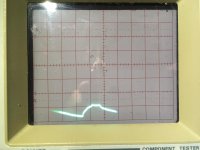
Let me have a think... I take it the incomplete trace is an artefact of the camera...
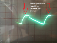
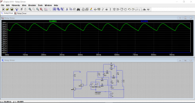
So if we take any two identical points on the cycle and look at the time between them we can calculate the frequency. At 5ms/div there are 4 squares between the same points.
Frequency is 1/T
So that gives 1/(0.005*4) which is 50Hz. Mains frequency.
And therein lies a possible clue 😉 Why is the ripple at 50Hz? That would also account for the lack of bias voltage on the 150k.
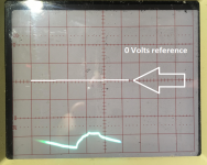
We have D605 and D606 which form a full wave rectifier. Each half cycle should be being used to produce the DC bias voltage and that means the ripple should be at 100Hz, not 50.
The two images below show what happens when one of those diodes isn't contributing. This is what you will need to check with the scope.
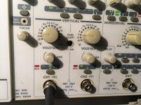
Remember chassis ground only for the scope
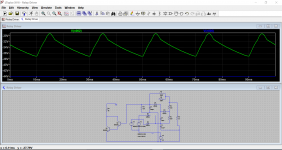
First simulation image shows the voltage on R416. Look at the time scale and voltage scale.
It is 10ms between identical parts of the cycle and so we get a frequency of 100Hz. The average DC voltage is in the -32 volt region.
Now look what happens when either of those diodes is missing and so one half of each mains cycle is not being rectified.
Now we something that looks remarkably like your measurement. So we need to explore this...
In the first instance you can do a careful visual and conductive ohms test to check there is no broken print anywhere. That means to each diode from the transformer and from each diode to wherever it goes on the board.
If that is OK then you use the scope to look at the raw AC on the diodes (from the transformer) and make sure it is getting there. Then look at the diode outputs and see what is happening.
So if we take any two identical points on the cycle and look at the time between them we can calculate the frequency. At 5ms/div there are 4 squares between the same points.
Frequency is 1/T
So that gives 1/(0.005*4) which is 50Hz. Mains frequency.
And therein lies a possible clue 😉 Why is the ripple at 50Hz? That would also account for the lack of bias voltage on the 150k.
We have D605 and D606 which form a full wave rectifier. Each half cycle should be being used to produce the DC bias voltage and that means the ripple should be at 100Hz, not 50.
The two images below show what happens when one of those diodes isn't contributing. This is what you will need to check with the scope.
Remember chassis ground only for the scope
First simulation image shows the voltage on R416. Look at the time scale and voltage scale.
It is 10ms between identical parts of the cycle and so we get a frequency of 100Hz. The average DC voltage is in the -32 volt region.
Now look what happens when either of those diodes is missing and so one half of each mains cycle is not being rectified.
Now we something that looks remarkably like your measurement. So we need to explore this...
In the first instance you can do a careful visual and conductive ohms test to check there is no broken print anywhere. That means to each diode from the transformer and from each diode to wherever it goes on the board.
If that is OK then you use the scope to look at the raw AC on the diodes (from the transformer) and make sure it is getting there. Then look at the diode outputs and see what is happening.
Attachments
Good morning! And thanks! Yes, the trace on the scope is incomplete because it flickers and the cam records only a bit of it.
your second image looks really like what I am seeing on the scope. Ok so I go hunting around the diodes... check continuity and have a look at the traces. I'll need to lift that wicked PS board from the three PS cap pins again...
and will report back.
I love my scope now!
your second image looks really like what I am seeing on the scope. Ok so I go hunting around the diodes... check continuity and have a look at the traces. I'll need to lift that wicked PS board from the three PS cap pins again...
and will report back.
I love my scope now!
🙂 Good 'innit 😀
If it is easier to get the probe in there then you could carefully do measurements first. See if you can find anything amiss or missing.
You should see the same thing on each end of each diode. If one is different then that is a clue something is wrong.
I'll look in a lot later this morning hopefully 🙂 Good hunting.
We found it. The relay problem.
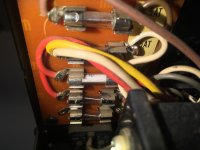
It was one of the two secondary transformer fuses (6,3A). Right at the beginning of the whole repair I had substituted one of them which had a wire inside and had obviously been molten; this other has sand inside, which looks good (pic, third from below; the one right at the bottom is a spare one), so I thought it was ok. The continuity test showed it was open :-(
So I visually checked the fuse right at the very beginning, but was misled.
I googled now that those quartz sand fuses might not show they're shot. The shot ones I looked at in my life looked all burnt.
So now the relay clicks 🙂 which is already music in my ears.
The right channel bias nonetheless remains zero, however, and doesn't change when I turn the preset pot... I had been hoping that it had been miraculously cured as well.
We have R412 and R415 not connected to the circuit at the moment (one lead raised). How should we proceed?
Attachments
Wonderful 🙂
You can see how sticking to the theory and how detailed measurement led to the cause of the problem.
You can build the relay section back up, resolder anything that was lifted etc. Put it all back to original condition.
The relay should still close provided the two inputs from the two channels are still at zero volts, in other words no DC offset on either channel.
So that is the first check, that the two channels have zero volts DC present at the 0.22 ohm resistor junction.
ok! thanks for being so patient with me. I find the way you approached it maximally helpful. And I learned A LOT.
I'll report back after having put everything back in place and checking both channels for DC.
I'll report back after having put everything back in place and checking both channels for DC.
No problem 🙂 and it was an interesting issue given the fact that DC measurements with a meter were going nowhere. The theory of how it operates was sound and yet it refused to work and so there had to be something we couldn't see (with a meter) going on.
And there was.
Now if we had started looking at the power amp first and instead of the relay driver we would probably have found the fuse problem early on... however 😀
And there was.
Now if we had started looking at the power amp first and instead of the relay driver we would probably have found the fuse problem early on... however 😀
Oh and I refrained from wanting the power amp first because I tried to abstain from the drive for instant gratification!
Truly interesting, also for me. It pays to have that long breath for a systematic approach. That was an impressive lesson in this.
Soldered the two resistors back in place. Relay engages. The left (good) channel settles at 41 mV DC offset. The right (bad) one shows only 0.1mV offset. Could this be a first clue?
ah, and I checked that funky SV04F diode D303 yesterday again out of circuit (with both leads free), and it read fine (OL in one direction, 2.1V in the other on the diode test setting).
D302 is new (the "death diode" substituted by two others in series, although it tested ok); D301 checked fine when I tested it a couple of days ago.
D302 is new (the "death diode" substituted by two others in series, although it tested ok); D301 checked fine when I tested it a couple of days ago.
Those double, triple and I think even quad diode packs have a bit of a reputation for failing by going open circuit.
If that happened then the bias would shoot up, most probably destructively.
The low offset of 0.1mv is either super good or there is a problem.
A couple of quick checks first. Measure the DC voltage across R312 and R313 and compare good and 'bad' channels. The voltages should be similar.
I would guess around 0.7 volts or so meaning that around 7 milliamps is flowing.
If that is OK then I think trying a speaker and series resistor is in order. Something around 100 ohm. Its just a case of seeing if there is clear audio present.
Remember that with 100 ohm in series the amplifier will clip long before anything seems loud. Just set the volume to normal positions on the dial and see if it plays OK.
Or you could try headphones.
ok. in any case the bias in the bad channel does not change even if I turn the pot.
"measure across" –– does it mean that the black and the read probes of my DMM are before and after the resistor? or black lead to ground and then measure twice per resistor, before and after it?
I was thinking that maybe there is another ripple problem in that channel so again the bias transistor does not turn on.
I guess I could test for audio also with my "audio probe": a lead in series with a cap wich I plug into the AUX in of another amp. helped me find many faults yet – in before-scope-times 🙂
ok. in any case the bias in the bad channel does not change even if I turn the pot.
"measure across" –– does it mean that the black and the read probes of my DMM are before and after the resistor? or black lead to ground and then measure twice per resistor, before and after it?
well probably the latter 🙂
Measure across just means one lead on one end of the resistor and the other lead on the other end. Meter only of course, not the scope.
Ideally you want the positive lead on the most positive end and the negative on the other. If you get it reversed you just get a negative reading instead.
You could try an audio tester but I'd probably prefer the probe load of resistor and speaker tbh. The tester is very high impedance and doesn't load anything.
Don't worry about no bias at this stage... we have to get that channel playing properly with or without bias.
well probably the latter 🙂
The reason we don't measure from ground to the resistor is simply because the readings alter all the time.
For example if the 44 volt rail is at 44 volts and the other end of the resistor is at 43.3v then we have 0.7 volts across the resistor.
What could go wrong... well in the time it takes you to move the lead and get the second reading the mains voltage might have altered a fraction up or down and so to the rails.
So you read 44v for the rail and then 44.6 at the other end... hmmm slight problem, the other end of the resistor is now higher than the supply was 🙂
Measuring across removes that issue. The voltage will stay constant even if the mains alters a bit.
OK I got it. Those were awfully fluctuating readings first.
Another thing learned.
The readings I have are also a bit weird:
Good channel (left):
R312 0.1V
R313 0.5V
Bad channel (right):
R362 0V
R363 0V
I checked if there is voltage on the main supply rails on the bad channel, yes, there is. I mean, there are the right voltages.
Last edited:
I tried headphones. Clear audio on the good channel. No audio on the bad one. Nothing, no sound, no hiss, no buzz.
That does look like a problem... so we measure and look for evidence of what might be amiss.
1/ Measure the voltage on each side of R316. We are measuring from ground now. Should be around +44 volts on each side.
2/ Measure the voltage on R320. Should be -44v each side.
3/ D301 and D302 are types I don't recognise, however D302 looks like it will be a double diode (two series diodes).
Compare channels but I think you should find around 1.2 volts across D302 (so not from ground now).
4/ D301 is a Zener and used to generate a stable voltage to connect R309 so it bias the upper transistors with a clean supply.
Just compare the voltage on D301 with the good channel. Reading from ground you should see +44v on the top end (stripy end if they have a stripe) and something like 30 volts on the other end. It all depends on the Zener voltage which will subtract from the +44v.
Just make sure both are similar.
- Home
- Amplifiers
- Solid State
- Sony TA-3650 power rail resistors burn