I'm using ARTA which allows for gated measurements. jReave recommended a couple papers from Jeff Bagby on what to actually measure. The port graphs are pretty wonky, I haven't figured out how to select the gating points for it yet.
What volume levels should I be taking my measurements at? I haven't seen any actual recommendations on that anywhere.
For the woofer and port near field measurements set the gate time to 100 msec (good down to ~ 10 Hz). As for the near field woofer and port volume - just make sure they are done at the same volume and don't cause clipping. You will be adjusting those levels to match your far field measurement. It's explained in the Bagby paper.
For the woofer and port near field measurements set the gate time to 100 msec (good down to ~ 10 Hz).
Please correct me if I'm wrong here ... but isn't the window size about how long it listens after the frequency specific burst and not the length of time it takes to play the burst itself?
For example: at 1khz the test tone takes about 3ms (3 cycles).
When the system is testing it enables the mic, plays the burst, waits the gate time, then closes for the next test point.
Or have I somehow misunderstood?
I followed Charlie Laub's instructions http://audio.claub.net/tutorials/FR measurement using ARTA.pdf For impulse measurements ARTA does three sine sweeps and averages them. You next look at the impulse response and tell it where to crop the display, then it calculates the response and phase from what remains.
Moondog55, I've been busy today so I almost let this one slip by.
That rule of thumb isn't about listening off-axis, it's about power response and room reflections. We primarily hear the on-axis response but our perception is also colored by room reflections. So if there is a small range in the FR before the tweeter response where the mid's off-axis response is weaker, we will perceive that as an overall dip in the FR in the listening position despite the fact that the on-axis FR might measure flat.
So if you can keep the FR as omni-directional as possible all the way up to where the tweeter finally starts to get directional, you will have a better sounding speaker.
OK Point taken I guess I am lucky in that my room is relatively non reflective due to fortuitive speaker placement and very expensive heavy drapes and probably why I favour 4" and 5" midrange drivers too without fully understanding why { the exception being the Tarkus and all its clones} so thanx for explaining that well.
So if you can keep the FR as omni-directional as possible all the way up to where the tweeter finally starts to get directional, you will have a better sounding speaker.
Providing, of course, that you are trying to design an omni-directional speaker. 😀
I don't think I've ever quite understood why we need that when in most cases we are within about 45 degrees of on-axis listening and in most rooms can't get more than 90 degrees off axis if we tried.
Why not tailor the speaker to direct sound forward in a flashlight-like pattern aimed at the listener? It would avoid a lot of indirect sound issues and particularly that all time bugaboo of the first reflection.
Putting on my "old gummer" hat I would remind you that "Back in my heyday speakers were placed against walls". They all worked into a half sphere and in some cases were designed for corner placement and worked into a quarter sphere. The L-100, Klipschorn, LaScala and Heresy are still some of the most sought after speakers today and none of them even pretended to be omnidirectional.
Please correct me if I'm wrong here ... but isn't the window size about how long it listens after the frequency specific burst and not the length of time it takes to play the burst itself?
For example: at 1khz the test tone takes about 3ms (3 cycles).
When the system is testing it enables the mic, plays the burst, waits the gate time, then closes for the next test point.
Or have I somehow misunderstood?
You are correct in that the window is how long it listens.
The length of listening is to capture one full wavelength at the lowest frequency being measured. the gate is the lesser of the length of the wavelength to be measured and vs when first reflection will arrive during that measurement to "muck it up". Hence why the longer the gate, the lower in frequency you can measure - but the further away the nearest boundary can be.
You are correct in that the window is how long it listens.
Thanks Dave ... Now I got a couple of speakers to drag out of my closet and re-measure. 🙄
Glitch (my avatar) would say... "Wal shucks ya learns somethin' new everday"
Last edited:
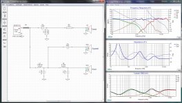
Here is an update of the Version 5 crossover design... V5B ... as it were.
This is not a major change, just some tweaking of parts values to get that last DB out of it... The efficiency is very high, almost 90db/w, there is almost no wasted current and the impedance is sitting at about 7 ohms.
As usual I followed the practice of letting the first part in any chain do the lions share of the work. This because it is in series and thus does not shunt power to ground. The shunt parts are used for fine tuning only, lest they end up drawing too much current.
When the measured driver files come available I will plug them into this and recalculate part values, hopefully without too much redesign.
Hope this helps...
Attachments
Looks really good again! I'm slowly figuring out this measurement thing. Hopefully I can have something useful in the next day or two.
I have a DATS 3 unit. Would impedance measurements in the cabinet be useful?
I have a DATS 3 unit. Would impedance measurements in the cabinet be useful?
Looks really good again! I'm slowly figuring out this measurement thing. Hopefully I can have something useful in the next day or two.
I have a DATS 3 unit. Would impedance measurements in the cabinet be useful?
Well, for me to do what I do, I need accurate FRD and ZMA files. Remember, my main skill here is electronics, there are others who know much more about box design and measurement than I do.
@Douglas Blake,
Very nice work on that crossover indeed!😀 I'm impressed that you achieved such a good response with only 8 components. I like that kind of minimalist approach.
Be Safe,
Rich
Very nice work on that crossover indeed!😀 I'm impressed that you achieved such a good response with only 8 components. I like that kind of minimalist approach.
Be Safe,
Rich
@Douglas Blake,
Very interesting and crossover design. I am still new to crossovers and struggling to understand the effects of different order of filters used and their effects on the polar response.
I see that in your design,
Tweeter is 2nd order (electrical)
Midrange is 3rd order
Woofer is 4th order.
How does this influence the phase of the outputs and ultimately the polar response?
Back in my training --last century 😱-- my instructor used to give us little design projects to see if we actually understood the lessons. He would tell us to work in two stages... "First get it to work AT ALL. Then take out everything that's not needed to keep it working." Stayed with me all this time...
Here is an update of the Version 5 crossover design... V5B ... as it were.
This is not a major change, just some tweaking of parts values to get that last DB out of it... The efficiency is very high, almost 90db/w, there is almost no wasted current and the impedance is sitting at about 7 ohms.
As usual I followed the practice of letting the first part in any chain do the lions share of the work. This because it is in series and thus does not shunt power to ground. The shunt parts are used for fine tuning only, lest they end up drawing too much current.
When the measured driver files come available I will plug them into this and recalculate part values, hopefully without too much redesign.
Hope this helps...
You've got some cancellation effects going on ~ 1500Hz with the midrange level being pulled down by out of phase woofer or tweeter (or both) behaviour. It's only 1 - 2 dB but I'd prefer to fix that at the cost of extra crossover components and possible crossover efficiency
You've got some cancellation effects going on ~ 1500Hz with the midrange level being pulled down by out of phase woofer or tweeter (or both) behaviour. It's only 1 - 2 dB but I'd prefer to fix that at the cost of extra crossover components and possible crossover efficiency
That would be a designer's choice.
The woofer is inverted the tweeter is not... they aren't technically out of phase, but there is a drop in reinforcement at that point in the curve. I looked at it and figured... OK I can get 89+ db out of this or I can get rid of a couple of minor issues and get 85. For the small difference of 1 or 2 db in frequency response I didn't think it worth the extra parts and seriously doubt it would be audible.
Of course... nothing stops you from working up your own design and posting it... Jeff might even prefer to have the choice...
@Douglas Blake,
Very interesting and crossover design. I am still new to crossovers and struggling to understand the effects of different order of filters used and their effects on the polar response.
I see that in your design,
Tweeter is 2nd order (electrical)
Midrange is 3rd order
Woofer is 4th order.
How does this influence the phase of the outputs and ultimately the polar response?
The biggest factor is the phase at the crossover point. Given the bizarre filter topology I suspect the midrange may "beam" just a little, but that remains to be seen. Please note that the woofer is inverted (wired backwards) to compensate for the phase issue it would have with the midrange at their crossover but the tweeter and mid are wired in phase so the high frequency dispersion should be about that of the drivers themselves.
With a crossover this simple, it will be interesting to see what Jeff measures after the build... (Provided, of course, he decides to use my design.)
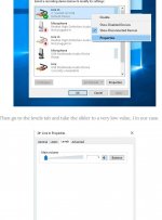
Somewhere in my measurements the levels are getting attenuated badly. Somewhere in one of the million pages I've read on measurement techniques over the past couple days I read to set the microphone level to 1 (1 out of 100) in Windows before opening ARTA ( I think this was in the ARTA manual). Is this correct?
Somewhere in my measurements the levels are getting attenuated badly. Somewhere in one of the million pages I've read on measurement techniques over the past couple days I read to set the microphone level to 1 (1 out of 100) in Windows before opening ARTA ( I think this was in the ARTA manual). Is this correct?
If you go into Control Panel->Sound->Recording->(Your) Microphone->Properties ... you may never find your way out, umm, wait, no that's not it... you will see there is a mic level and a mic boost for your microphone. I'm pretty sure you want the mic level at max to let the software control it, but the boost at 0 so that you aren't getting artificial enhancements.
That sounds more reasonable. This is where i read it. Quasi anechoic loudspeaker measurements Part 1 | Audio Judgement
Attachments
Feel free to list the shortcomings of your own design. We expect that not all crossover examples are 'final designs', and some are for educational purposes.That would be a designer's choice.
Peer review is an accepted procedure, it helps all round.
- Home
- Loudspeakers
- Multi-Way
- Crossover Critique