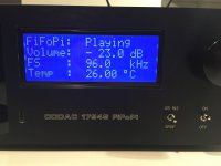
Need indication of FS on track being played?
As MP always said: And now for something completely different! ... but still on topic 😉
Roon and also other players / Linux based boards etc are not always capable to supply the FS data from the track playing. Like 44.1kHz or 192kHz etc
As I already have a nice piece of code on my Arduino (based DDDAC), showing the FS on the display I wanted it back, now that I also use Roon/RaspberryPI who are not supplying that information...
Also some DDDAC users who use the LED strip/board/module from the mainboard will have no LED indicators anymore when not using the WaveIO, but a Berry streamer…
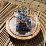
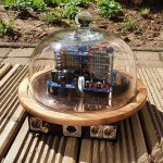
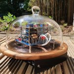
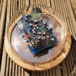
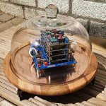
So I made a simple stand alone solution, which can be used for any other application as well (where you want to know what FS actually is playing)
I just took a standard Arduino UNO and "simulated" the standard Output of the Waveio for the LED indicators.
It works like this:
The arduino is connected to the FS (or L/R) pin from the I2S signal
Using a library which measures the actual frequency of the signal
The program is testing this frequency if it falls within certain limits and will put an output pin "HIGH" for the respective FS value. So it is NOT displaying the actual frequency, it uses the actual frequency to decide whether it is 44.1 or 96 or whatever
Below is a sketch how it is connected and also the Arduino Code.
For some stupid reason I can NOT upload the original Arduino x.ino file, so I changed it into a text file. Just copy and paste this in the Arduino compiler. People who use Arduino know how to do things like this.
This is DIY so no support, other than questions for clarification.
any other clever code ideas are welcome, just reply or send me a PM
If you have NO clue how to do Arduino stuff and you are desperate to get it anyway, just PM me - I might be able to help
have fun with it 😎
Doede
PS: Arduino controlled stuff always makes things easy, as you will have noticed the temperature indication (inside the chassis) 2$ sensor, just attach, write some code - ready 😛
PS2: Tomorrow I will get the front and back plate from Schaefer... So I can complete the new DDDAC... It already burned in for a week, so good to go
As MP always said: And now for something completely different! ... but still on topic 😉
Roon and also other players / Linux based boards etc are not always capable to supply the FS data from the track playing. Like 44.1kHz or 192kHz etc
As I already have a nice piece of code on my Arduino (based DDDAC), showing the FS on the display I wanted it back, now that I also use Roon/RaspberryPI who are not supplying that information...
Also some DDDAC users who use the LED strip/board/module from the mainboard will have no LED indicators anymore when not using the WaveIO, but a Berry streamer…
So I made a simple stand alone solution, which can be used for any other application as well (where you want to know what FS actually is playing)
I just took a standard Arduino UNO and "simulated" the standard Output of the Waveio for the LED indicators.
It works like this:
The arduino is connected to the FS (or L/R) pin from the I2S signal
Using a library which measures the actual frequency of the signal
The program is testing this frequency if it falls within certain limits and will put an output pin "HIGH" for the respective FS value. So it is NOT displaying the actual frequency, it uses the actual frequency to decide whether it is 44.1 or 96 or whatever
Below is a sketch how it is connected and also the Arduino Code.
For some stupid reason I can NOT upload the original Arduino x.ino file, so I changed it into a text file. Just copy and paste this in the Arduino compiler. People who use Arduino know how to do things like this.
This is DIY so no support, other than questions for clarification.
any other clever code ideas are welcome, just reply or send me a PM
If you have NO clue how to do Arduino stuff and you are desperate to get it anyway, just PM me - I might be able to help
have fun with it 😎
Doede
PS: Arduino controlled stuff always makes things easy, as you will have noticed the temperature indication (inside the chassis) 2$ sensor, just attach, write some code - ready 😛
PS2: Tomorrow I will get the front and back plate from Schaefer... So I can complete the new DDDAC... It already burned in for a week, so good to go
Attachments
My new DDDAC1794S FiFoPi version
As promised…
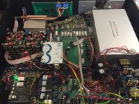
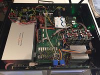
This is now my 5th DDDAC I built for my own use. It contains many ideas I collected, the tests I did, the tips I got here from the community, etc., etc.…
This is in short how it is built up:
4 Deck DDDAC, almost completely standard, but with Non Magnetic Silver Resistors for I/V
Roon Endpoint Raspberry PI3B with Ropieee
WaveIO USB input
SPDIF input
Ian Canada FiFoPi for reclocking the PI and the WaveIO I2S Signal
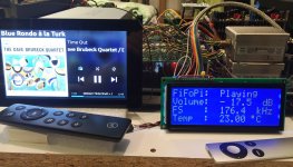
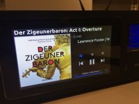
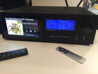
Ropieee based touch screen display as Roon Remote
RF Remote control for Roon and IR Apple thingy for the DAC, menu and volume control
Sowter DDDAC special version TVC output with 18 taps and 36 Volume levels (added -20dB)
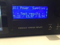
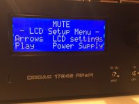
All Arduino MEGA2560 controlled for IR remote and front panel switches including test and setup menu
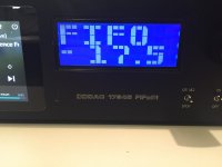
A separate Arduino UNO to measure the actual FS signal frequency and generate the sample frequency indication from the track in the display (like “44.1kHz” or “192kHz”).
Audio Creative “Magic Power Supply” (CLC type passive) for the DAC and the FiFoPi clocks
FiFoPi isolated clock section 3,3 V supply with a LT3045 LDOVR 78xx regulator
Input side of FiFoPi 4,3 Volt with a LT3045 LDOVR 78xx regulator – also feeding WaveIO I2S isolated output
LM317 9Volt Module for the Arduinos, FiFoPi input and the TVC control board
5V/4A SMPS to feed the raspberry PI3Bs, the display, the WaveIO and the selector relays board
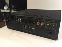
The DAC can be streamed to by Roon through Ethernet cable or through Wi-Fi ... That is why I removed the on board mini antennas of the two raspberry PI3B and extended the antenna in/output with a coax cable to the outside antennas. (I use two PI, one for the Display and one for the streaming)
The front and back are made by Schaefer in Berlin
The chassis and volume knob are from Modus HiFi in Italy
Next step: easy listening, enjoying the music and do compare tests with the 5 volt supply on the mainboard (I have a Bluetooth controlled A_B comparison board to do this, so any combination of two 5 volt regulators, VDO super regs etc., can be compared on the fly while music plays
Secondly, see if I can hear any SQ difference between Wi-Fi and Ethernet operation…
So far it was BIG fun again to build up this somewhat unusable DDDAC
As promised…
This is now my 5th DDDAC I built for my own use. It contains many ideas I collected, the tests I did, the tips I got here from the community, etc., etc.…
This is in short how it is built up:
4 Deck DDDAC, almost completely standard, but with Non Magnetic Silver Resistors for I/V
Roon Endpoint Raspberry PI3B with Ropieee
WaveIO USB input
SPDIF input
Ian Canada FiFoPi for reclocking the PI and the WaveIO I2S Signal
Ropieee based touch screen display as Roon Remote
RF Remote control for Roon and IR Apple thingy for the DAC, menu and volume control
Sowter DDDAC special version TVC output with 18 taps and 36 Volume levels (added -20dB)
All Arduino MEGA2560 controlled for IR remote and front panel switches including test and setup menu
A separate Arduino UNO to measure the actual FS signal frequency and generate the sample frequency indication from the track in the display (like “44.1kHz” or “192kHz”).
Audio Creative “Magic Power Supply” (CLC type passive) for the DAC and the FiFoPi clocks
FiFoPi isolated clock section 3,3 V supply with a LT3045 LDOVR 78xx regulator
Input side of FiFoPi 4,3 Volt with a LT3045 LDOVR 78xx regulator – also feeding WaveIO I2S isolated output
LM317 9Volt Module for the Arduinos, FiFoPi input and the TVC control board
5V/4A SMPS to feed the raspberry PI3Bs, the display, the WaveIO and the selector relays board
The DAC can be streamed to by Roon through Ethernet cable or through Wi-Fi ... That is why I removed the on board mini antennas of the two raspberry PI3B and extended the antenna in/output with a coax cable to the outside antennas. (I use two PI, one for the Display and one for the streaming)
The front and back are made by Schaefer in Berlin
The chassis and volume knob are from Modus HiFi in Italy
Next step: easy listening, enjoying the music and do compare tests with the 5 volt supply on the mainboard (I have a Bluetooth controlled A_B comparison board to do this, so any combination of two 5 volt regulators, VDO super regs etc., can be compared on the fly while music plays
Secondly, see if I can hear any SQ difference between Wi-Fi and Ethernet operation…
So far it was BIG fun again to build up this somewhat unusable DDDAC
Attachments
-
 DDDAC1794S FiFoPi - 30.JPG342.4 KB · Views: 184
 -
 DDDAC1794S FiFoPi - 29.JPG450.8 KB · Views: 178
 -
 DDDAC1794S FiFoPi - 28.JPG413.8 KB · Views: 183
 -
 DDDAC1794S FiFoPi - 27.JPG340.3 KB · Views: 228
 -
 DDDAC1794S FiFoPi - 24.JPG325.4 KB · Views: 311
 -
 DDDAC1794S FiFoPi - 23.JPG687 KB · Views: 357
 -
 DDDAC1794S FiFoPi - 22.JPG600.3 KB · Views: 555
 -
 DDDAC1794S FiFoPi - 19.JPG455.6 KB · Views: 552
 -
 DDDAC1794S FiFoPi - 18.JPG365.9 KB · Views: 560
 -
 DDDAC1794S FiFoPi - 17.JPG300.9 KB · Views: 550
Really fantastic work Doede 😀
How did you connect the Pi 7 inch display to your front panel please?
To change the menu on the smaller display you are using the Apple remote to do that?
Thanks
Simon 🙂
How did you connect the Pi 7 inch display to your front panel please?
To change the menu on the smaller display you are using the Apple remote to do that?
Thanks
Simon 🙂
Really fantastic work Doede 😀
How did you connect the Pi 7 inch display to your front panel please?
To change the menu on the smaller display you are using the Apple remote to do that?
Thanks
Simon 🙂
Thanks Simon 🙂 I just glued it in with locktight second glue 😛
yep, the smaller display is the dac controll with the arduino MEGA and I use the apple remote for that in parallel to the fron controls (source selection, setup & volume)
Attachments
Last edited:
Right now its clear 🙂
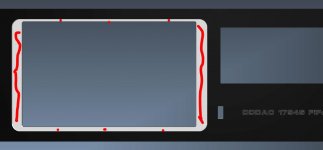
And for the smaller display you used stand off pillers mounted to the back of the front panel? This is what i did for my display mounting
And for the smaller display you used stand off pillers mounted to the back of the front panel? This is what i did for my display mounting
Right now its clear 🙂
And for the smaller display you used stand off pillers mounted to the back of the front panel? This is what i did for my display mounting
Correct Simon, just 4x 5mm M2,5 standoffs and glued with 2 component resin epoxy glue - just smear a big drop around the stand offs… happens to fit exactly in a 4mm front panel - to have the front of the LCD in line with the front panel - 😀
4 Deck DDDAC, almost completely standard, but with Non Magnetic Silver Resistors for I/V
How would you characterize the sound of the Audio Note Silver Tantalum nonmagnetic resistors? Did you use 0.5 watt or 2 watt?
How would you characterize the sound of the Audio Note Silver Tantalum nonmagnetic resistors? Did you use 0.5 watt or 2 watt?
They are new to me. I am not ready yet with the burn in and listening - but will come back to this for sure 🙂
They are new to me. I am not ready yet with the burn in and listening - but will come back to this for sure 🙂
2w or 0.5w Doede?
no... I was unclear again I believe 😱
So I made a drawing 😎
Question Doede, did you notice any negative influence of the 5v SMPS (for powering the RPI and other equipment) in the overal SQ?
Question Doede, did you notice any negative influence of the 5v SMPS (for powering the RPI and other equipment) in the overal SQ?
Nothing I could hear / notice....
What I can hear is the 3,3 V on the FiFoPi and the 5 Volt on the mainboard
But more to come on the latter… 😉
Has anyone tried to supply the DDDAC mainboard with 13.2V instead of 12V? I'm contemplating to build one of IanCanada's LiFePO4 supplies. Thanks.
Has anyone tried to supply the DDDAC mainboard with 13.2V instead of 12V? I'm contemplating to build one of IanCanada's LiFePO4 supplies. Thanks.
works fine, no problem….
Hi there,
For a good friend of mine i just finished rebuilding and upgrading his "old school" 2 (Tent) deck WaveIO DDdac 1794 NOS with Cinemag 15/15b's.
Very happy with the result, both builder and friend 😀
For a good friend of mine i just finished rebuilding and upgrading his "old school" 2 (Tent) deck WaveIO DDdac 1794 NOS with Cinemag 15/15b's.
- Added 2 decks
- Replaced 8 x LF33 with LDOVR LT3045
- Rload resistors Audio Note Tantalums non magnetic 33r
- Soldered uFL pigtails to I2s
- Added ALLO USbridge sig.
- Added FiFoPi with Accusilicon clocks
- LDOVR LT3045 3,3V with R58 R59 upgrade
Very happy with the result, both builder and friend 😀
Attachments
-
 IMG_20200429_160910_226.jpg196.8 KB · Views: 177
 -
 IMG_20200429_160910_224.jpg228.6 KB · Views: 170
 -
 IMG_20200429_160910_222.jpg234.7 KB · Views: 176
 -
 IMG_20200429_160910_068.jpg189.1 KB · Views: 185
 -
 IMG_20200429_160910_060.jpg213.4 KB · Views: 361
 -
 IMG_20200429_160910_051.jpg212.2 KB · Views: 369
 -
 IMG_20200429_160910_050.jpg207.6 KB · Views: 374
 -
 IMG_20200429_160910_049.jpg211.8 KB · Views: 377
 -
 Startingpoint.jpg433.2 KB · Views: 381
 -
 in working order.jpg86.7 KB · Views: 188
- Home
- Source & Line
- Digital Line Level
- A NOS 192/24 DAC with the PCM1794 (and WaveIO USB input)