As promised…
This is now my 5th DDDAC I built for my own use. It contains many ideas I collected, the tests I did, the tips I got here from the community, etc., etc.…
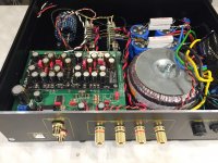
This is in short how it is built up:
4 Deck DDDAC, almost completely standard, but with Non Magnetic Silver Resistors for I/V
Roon Endpoint Raspberry PI3B with Ropieee
WaveIO USB input
SPDIF input
Ian Canada FiFoPi for reclocking the PI and the WaveIO I2S Signal
Ropieee based touch screen display as Roon Remote
RF Remote control for Roon and IR Apple thingy for the DAC, menu and volume control
Sowter DDDAC special version TVC output with 18 taps and 36 Volume levels (added -20dB)
All Arduino MEGA2560 controlled for IR remote and front panel switches including test and setup menu
A separate Arduino UNO to measure the actual FS signal frequency and generate the sample frequency indication from the track in the display (like “44.1kHz” or “192kHz”).
Audio Creative “Magic Power Supply” (CLC type passive) for the DAC and the FiFoPi clocks
FiFoPi isolated clock section 3,3 V supply with a LT3045 LDOVR 78xx regulator
Input side of FiFoPi 4,3 Volt with a LT3045 LDOVR 78xx regulator – also feeding WaveIO I2S isolated output
LM317 9Volt Module for the Arduinos, FiFoPi input and the TVC control board
5V/4A SMPS to feed the raspberry PI3Bs, the display, the WaveIO and the selector relays board
The DAC can be streamed to by Roon through Ethernet cable or through Wi-Fi ... That is why I removed the on board mini antennas of the two raspberry PI3B and extended the antenna in/output with a coax cable to the outside antennas. (I use two PI, one for the Display and one for the streaming)
The front and back are made by Schaefer in Berlin
The chassis and volume knob are from Modus HiFi in Italy
Next step: easy listening, enjoying the music and do compare tests with the 5 volt supply on the mainboard (I have a Bluetooth controlled A_B comparison board to do this, so any combination of two 5 volt regulators, VDO super regs etc., can be compared on the fly while music plays
Secondly, see if I can hear any SQ difference between Wi-Fi and Ethernet operation…
So far it was BIG fun again to build up this somewhat unusable DDDAC
Hey Doede - If it is alright, could you indicate that end to end, what would be the total cost of this build (including chasis, everything,etc.)?
Cheers
Hey Doede - If it is alright, could you indicate that end to end, what would be the total cost of this build (including chasis, everything,etc.)?
Cheers
very roughly around 3.500 Euro
....of course Doede has built a DAC with Pre amp built in too
Thanks for pointing that out Simon. The DAC part of it is more like 2200.
And from that easily 500 euro is windows dressing with special Schaefer panels and the RoPieee display
just in case any one wants to comment on this topic and my post ;-)
😛
blind test no difference thread post6189241
😛
blind test no difference thread post6189241
Some people feel ashamed by their inability to distinguish what they hear, insulted that they were deceived by hi-fi industry charlatans, and/or resentful that people with greater financial means appear to be enjoying an experience that is difficult to procure. Sometimes these feelings fuel a personal crusade, carried out on audio forums, to correct some perceived injustice in the world.
All turntables sound the same...
All turntables pretty much sound the same... | Steve Hoffman Music Forums
All phono stages sound the same...
Hardly any sonic difference between 7 phono preamps- Vinyl Engine
All amplifiers sound the same...
Do all amplifiers sound the same? | AVForums
All cables sound the same...
The Truth About Interconnects and Cables | Audioholics
I could certainly go on to include capacitors, resistors, and digital music servers ("bits is bits"). Even speakers are fair game; the OP recently started a similar thread on those. (BLINDTEST: Midrange 360-7200hz, NO audible difference whatsover.)
Don't worry about this. It's fine. Let these people do their thing, and let us ponder why they remain so intent on spending their time on audio forums. Particularly one where every page says:
diyAudio: projects by fanatics, for fanatics
Long live DDDAC. The OP from that thread and I even agree on one thing -- we have never heard a DAC that sounds better.
Hi fellow DDDac-builders.
Does anyone have any idea about what could cause a crackling noise in my right channel? It sound kind of like vinyl crackling and popping noise along the music.
The strange thing is that it only happens when using the positive output. I'm using standard capacitors in the output at the moment.
So, only right channel and only using the POS-output.
It seems to follow the music-volume and stops between music-track and when not playing.
The crackling DDDac-board had a bad solder-pad and the left-channel (I think) 4.7ohm resistors was 4.7Mohm??? I have corrected the solder-pad and replaced both resistors.
Both bias-voltages have been checked and is around 40mV.
Anyone?
Anyone?
Background info if interested...
I got hold of another DDDac-users scrap yard of older Dac-boards and some newer but defective stuff. The purpose is to build another extra/test DDDac for little money and to learn more about electronics.
The pcb's are these:
- 1 newer defective MB with no sound coming through. Will probably need some smd replacements.
- 1 newer Tent DDDac-board with the crackling noise.
- 1 12V DDDac standard psu. Now repaired by changing the TIP122 🙂
- 2 old-style DDDac board in working condition.
- 1 old-style DDDac board with only sound in left channel.
...and how do a test this if the mainboard is dead? ...On my other main DDDac MB which have been disassembled because I'm going to upgrade this from a single to a quad-decker, using 3 new and fresh boards bought from Audio-Creative.
Regards...
In general, when faced with an intermittent problem I will start with when and where the symptoms started and work back. Sometimes there is a clue in what you did just before the problem started. If you changed cables perhaps it is a bad connection at the connector etc.
Given that the used boards may have been subject to any imaginable abuse or tinkering you need to be very thorough in inspecting them for damage or mistakes made during previous work. I have been working electronic maintenance for over 40 years and have found many faults by shutting down a piece of equipment, pulling the plug from the wall and doing a thorough visual inspection. Take nothing for granted and leave no stone unturned. Shorts, damaged parts and bad solder joints often seem to hide in areas you cannot see with a casual glance. Sense of smell will also tell you if there are parts burnt or running too hot.
I do a lot of troubleshooting with an ohm meter. That way the device is unpowered and you have little chance of shorting something out with meter probes. Check for shorts on the power supply buses and at the inputs to the on board regulators.
After an unpowered inspection and basic ohm meter checks I will then go to powered troubleshooting.
One thing I seem to remember about DDDAC is that the DAC boards will be damaged if powered up while there is no clock signal to the board. This fact may be in the assembly documentation for the kit version. Keep this in mind as you are thinking of troubleshooting individual dac boards. I would think you should start with the main board only- no DAC boards mounted and using the extensive documentation available, verify that it is working properly and supplying all the signals and power the dac boards need. Then I would check all the dac boards passively and make certain there were no shorts on inputs/outputs and power connections before even thinking about installing one on the main board. Then add them one at a time to see if they function. I have never had to troubleshoot a DDDAC so I don’t know all the things to try but I would follow the basic plan above as a general guide.
Last edited:
diyAudio: projects by fanatics, for fanatics
HaHa, yes the way things are going around here we might have to change
that soon... reformed fanatics.
Long live DDDAC. The OP from that thread and I even agree on one thing -- we have never heard a DAC that sounds better.
Has anyone had a chance to compare DDDAC to latest Topping D90?
Thanks,
TCD
diyAudio: projects by fanatics, for fanatics
Long live DDDAC. The OP from that thread and I even agree on one thing -- we have never heard a DAC that sounds better.
Couldn't agree more

Hi...
@Bfpca Thanks for your general troubleshooting advice. I believe I had done most of it already but gave it another go.
I started thinking a bit more and took another hard look at the schematics. Since sound was fine on the Neg. output I figured that the problem couldn't be on the digital side. The Pcm1794 receives one I2S signal for both Pos and Neg outputs. I also measured the regulators again and they seemed fine. However, I'm not quite sure where to measure the Tent regulators 8V output.
I figured the problem most be on the analog side and here are actually only two possibilities. The right-side Pcm1794 chip or the IV-resistors.
Changed the 133ohm resistors on the right side to some new cheap carbon 1/4W resistors and the problem disappeared 🙂
...then changed the first ones back again, and sound was still fine? Doh!!!
Maybe a bad solder connection here or in another few places I have resoldered today.
The Dac motherboard have been assembled and disassembled from the case 10 times today... while also troubleshooting a spdif problem with Doedes help.
Interesting evening!!!
Hi...
@Bfpca Thanks for your general troubleshooting advice. I believe I had done most of it already but gave it another go.
I started thinking a bit more and took another hard look at the schematics. Since sound was fine on the Neg. output I figured that the problem couldn't be on the digital side. The Pcm1794 receives one I2S signal for both Pos and Neg outputs. I also measured the regulators again and they seemed fine. However, I'm not quite sure where to measure the Tent regulators 8V output.
I figured the problem most be on the analog side and here are actually only two possibilities. The right-side Pcm1794 chip or the IV-resistors.
Changed the 133ohm resistors on the right side to some new cheap carbon 1/4W resistors and the problem disappeared 🙂
...then changed the first ones back again, and sound was still fine? Doh!!!
Maybe a bad solder connection here or in another few places I have resoldered today.
The Dac motherboard have been assembled and disassembled from the case 10 times today... while also troubleshooting a spdif problem with Doedes help.
Interesting evening!!!
Good news! I think we have all been there. Building something and then having to take it apart again and again to fix something. It usually happens to me when I have built something in an enclosure that makes it really difficult to take it apart.
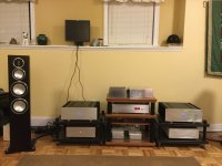
Getting some listening in right now actually. My entire system is DIY except for the speakers. I always built my own and recently bought a pair of Monitor Audio gold 300. It took a while for me to get them broken in and they are very revealing. The DDDAC shines through this system. Best sound I have ever had by far. Playing Bill Charlap right now. Live at the Village Vanguard.
DDDAC balanced out to a First Watt Balanced BA3 preamp, Monoblock First Watt F5 turbo V3 with separate power supplies for about 70wpc Class at 8 ohms. That is the DDDAC on the centre rack top shelf. Separate power supply box with an LC filtered unregulated supply. All the regulators are placed as close as possible to the DDDAC main board. I’m using a Wave I/o and USB from a Mac Mini through a W4S recovery USB interface to the Wave IO. Still astounded at times by how real this system can sound!
I have attached a picture of the current view from my listening chair.
Attachments
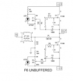
I will build my 4deck DDDAC with Sowters over the next few weeks, which will feed into my trusted First Watt F6. Now, this is the original F6 with a jfet buffer and semisouth SiC output. The low impedance of the DDDAC should allow me to bypass the buffer. Can I feed the transformer--coupled DDDAC output directly into the F6 phase splitting transformer? I don't fully understand what instabilities may occur when one transformer feeds into the primary of another transformer. Thanks
I will build my 4deck DDDAC with Sowters over the next few weeks, which will feed into my trusted First Watt F6. Now, this is the original F6 with a jfet buffer and semisouth SiC output. The low impedance of the DDDAC should allow me to bypass the buffer. Can I feed the transformer--coupled DDDAC output directly into the F6 phase splitting transformer? I don't fully understand what instabilities may occur when one transformer feeds into the primary of another transformer. Thanks
You can use the Sowter also as splitting Phase transformer - it has a center tap (normally not used, but here you can.
my 2 cents on your question If want to keep the transformer in the F6 doing the job:
just put a resistor at the F6-primary of say 100k and a 10k at the output of the Sowter. (both in their respective chassis of course)
ok, forget my comments… i did not knew the F6 in detail - good I had a look.
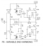
this is not a phase splitting setup - it is a d2 reducer….
you can omit the buffer it seems (maybe), but than you go in single ended. I am not 100% sure on the whole thing and this goes beyond this thread, so please check google or the Pass forums?
Attachments
Still a work in progress, but getting there.
Last week I got the second deck to make and put it on.
But also got me thinking of using a display, but did not want de RaspBerry screen, because of the lower resolution.
So I ordered this on, it has the instructions to make it work on a Raspberry, so just copy past this in de config and
7“ LCD Display - Joy-IT

And the second deck
When you do not have 68R resistors, just use the original 133R parallel to 3 parallel 390R to get "close enough"


And now with 68R 1W Takman Carbonfilm resistors

Last week I got the second deck to make and put it on.
But also got me thinking of using a display, but did not want de RaspBerry screen, because of the lower resolution.
So I ordered this on, it has the instructions to make it work on a Raspberry, so just copy past this in de config and
7“ LCD Display - Joy-IT
And the second deck
When you do not have 68R resistors, just use the original 133R parallel to 3 parallel 390R to get "close enough"
And now with 68R 1W Takman Carbonfilm resistors
I will build my 4deck DDDAC with Sowters over the next few weeks, which will feed into my trusted First Watt F6. Now, this is the original F6 with a jfet buffer and semisouth SiC output. The low impedance of the DDDAC should allow me to bypass the buffer. Can I feed the transformer--coupled DDDAC output directly into the F6 phase splitting transformer? I don't fully understand what instabilities may occur when one transformer feeds into the primary of another transformer. Thanks
The low DDDAC impedance you are referring to will be non-linear across the audio range, hence it is much better to keep that JFETs' buffer. The F6 is single-ended input amplifier. So, DAC transformer balanced-to-single ended, and then straight to F6 input (unmodified F6 input).
What to do with old "scrap" DDDACs?
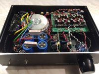
Inspired by the posts on getting some old stuf to work again, I heated up the soldering iron 😉
Many years ago a built a USB-Power-DAC with my early days usb-TDA1543 DAC and two UCD-180 modules. It has a "normal" analog input as well. I uses it in my home-office at a set of B&W bookshelf format speakers to have some music while working. I also used it sometimes for dance parties.
Problem was it only went to 48kHz and the output voltage was pretty low, so I could not drive the amplifier to full power 🙁 So I took a good look in the scrap box and found a mainboard where the spdif section was defective and an old dac module 1st generation I used for some test purpose some time ago. I also happened to have a Waveio with defective isolated output and no spdif.
But, combined it still worked as USB - I2S dac version.
I used the POS and NEG output to go straight into the balanced input of the UCD180 class D modules. Works like a charm, costed "nothing" and I had a good rainy Sunday afternoon 😀
and... finally FULL power output 😎
…
Attachments
Last edited:
Hey Doede, time put to good use. So the analog in means it acts as a preamp and tvc used are for volume control. As a dac, it gets used when you supply USB in, correct?Inspired by the posts on getting some old stuf to work again, I heated up the soldering iron 😉
Many years ago a built a USB-Power-DAC with my early days usb-TDA1543 DAC and two UCD-180 modules. It has a "normal" analog input as well. I uses it in my home-office at a set of B&W bookshelf format speakers to have some music while working. I also used it sometimes for dance parties.
Problem was it only went to 48kHz and the output voltage was pretty low, so I could not drive the amplifier to full power 🙁 So I took a good look in the scrap box and found a mainboard where the spdif section was defective and an old dac module 1st generation I used for some test purpose some time ago. I also happened to have a Waveio with defective isolated output and no spdif.
But, combined it still worked as USB - I2S dac version.
I used the POS and NEG output to go straight into the balanced input of the UCD180 class D modules. Works like a charm, costed "nothing" and I had a good rainy Sunday afternoon 😀
and... finally FULL power output 😎
…
- Home
- Source & Line
- Digital Line Level
- A NOS 192/24 DAC with the PCM1794 (and WaveIO USB input)