So the 24AWG should be fine, right? Or have I learned just enough to be dangerous?
That's rated at 100V 2.9A so yes according to spec it's fine for the 30V 200mA of the Pearl 2.
Although the circuit requirement is 100mA, this is more about peak current loads of a very short duration. 6 feet of 20 AWG has a bit less that half the resistance (.061 ohms) of 24 AWG (.154 ohms).
So using 24AWG cuts the power supply's ability to deliver peak currents in half. Part of the reason Wayne's PS schematic shows a 50 watt transformer when a 3 watt transformer could theoretically deliver 100mA.
So using 24AWG cuts the power supply's ability to deliver peak currents in half. Part of the reason Wayne's PS schematic shows a 50 watt transformer when a 3 watt transformer could theoretically deliver 100mA.
The Pearl 2 PCBs have so much local capacitance on them that this will never be an issue.
And that's not including the 20,000uF worth of filter caps, per channel, before the regulators. 🙂 🙂 🙂
And that's not including the 20,000uF worth of filter caps, per channel, before the regulators. 🙂 🙂 🙂
6L6:
So even this little 5 watt transformer would do the job?
70025K Acme Electric/Amveco/Actown | Transformers | DigiKey
So even this little 5 watt transformer would do the job?
70025K Acme Electric/Amveco/Actown | Transformers | DigiKey
I, personally, wouldn't use a 5 VA transformer when building a Pearl II, because 5VA doesn't offer an adequate margin of safety (a/k/a overkill) for my tastes.
The DC voltage at the bridge rectifier output is ±30V. The discussion of the Pearl II circuit on the Pass DIY website (link) says it draws 100mA per rail.
So that's (30V * 0.1 amp) = 3 watts drawn from the positive rail, and another (30V * 0.1 amp) = 3 watts drawn from the negative rail. 6 watts total.
Since I like to have a factor of two safety margin, (Prated / Pdrawn) >= 2, I would select a transformer rated 12VA or higher. Perhaps, something like one of these
Figuring that Pearl2 pula about 50mA pee channel, the 5VA would be running about 100% all the time.
Like Mark, I’d want at least 100% headroom so the transformer is at 1/2 rated or less. It’s not about headroom, it’s about a non stressed little transformers.
I like the 50VA Antek because they are the smallest that they offer that are shielded. I wish they made one smaller with shield.
Like Mark, I’d want at least 100% headroom so the transformer is at 1/2 rated or less. It’s not about headroom, it’s about a non stressed little transformers.
I like the 50VA Antek because they are the smallest that they offer that are shielded. I wish they made one smaller with shield.
No, sorry. Not yet.
Some people have been using perf board for the bridge diodes and caps etc. One could just use a larger piece I suppose.
Some people have been using perf board for the bridge diodes and caps etc. One could just use a larger piece I suppose.
FS series also available with dual primaries for those who need 230VAC input.
Class B instead of Class 3, not that it matters much for DIY. Also, 20 watt is about $8 less USD than the Amgis/Talema 15 watt toroids (which are not available from Mouser):
https://catalog.triadmagnetics.com/Asset/FS48-400.pdf
FS48-400 Triad Magnetics | Mouser
Class B instead of Class 3, not that it matters much for DIY. Also, 20 watt is about $8 less USD than the Amgis/Talema 15 watt toroids (which are not available from Mouser):
https://catalog.triadmagnetics.com/Asset/FS48-400.pdf
FS48-400 Triad Magnetics | Mouser
I suggested the "-C2" version since it was what dropped out of my search for components for a remote raw power supply in the vein of Gary Galo's suggestions for the Jung Didden regulators.
https://refsnregs.waltjung.org/Regs_for_High_Perf_Audio_4.pdf
Galo suggested that transformers with a higher HiPot rating would be better than toroids.
These Triads have voltages suitable for +/-24VDC regulation and VA ratings in the right ballpark for preamps like the Leach, Marsh and Pearls (which are what I've been interested in).
Is there any benefit to using dual primaries even if you hook 'em up in parallel for 120V?
Gary Galo says
Here is an extremely easy way to vastly decrease the capacitive coupling between the AC mains (primary side) and the dual secondary outputs. It adds only two electronic components and requires no modifications to the printed circuit boards. Schematic below.
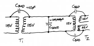
"T2" is the existing power transformer, with 115V primary and dual 22V secondaries. To that, we add new components "T1" and "Cgood". T1 is a 1-to-1 transformer, with 115V input and 115V output. Cgood is an 0.1uF (100 nanofarads ; 100,000 picofarads) capacitor.
As Gary Galo says, there exists capacitive coupling between primary and secondary of every transformer. I have drawn it as "Cbad" in the schematic. Its magnitude is somewhere between 1pF and 100pF depending on the physical geometry and construction details of the transformer.
Cbad forms the upper leg of a (capacitive) voltage divider; the lower leg is Cgood. Since the impedance of Cgood is a factor of ten thousand lower than the impedance of Cbad, mains borne noise and RF interference is attenuated by a factor of ten thousand times. This is a far greater improvement than you can ever get by merely switching from a single toroidal transformer to a single split-bobbin transformer.
And it's simple.
And if you are truly insane, you can cascade N of these 1-to-1 transformers in series, and get attenuation of (10,000 raised to the power N) times.
_
... Signal Transformers' A-41 series offers even more effective high-frequency noise attenuation. These dual-bobbin designs have two independent primary and secondary bobbins. This greatly reduces the capacitive coupling between them, which is extremely important for attenuation of common mode noise." {emphasis added by me}
Here is an extremely easy way to vastly decrease the capacitive coupling between the AC mains (primary side) and the dual secondary outputs. It adds only two electronic components and requires no modifications to the printed circuit boards. Schematic below.
"T2" is the existing power transformer, with 115V primary and dual 22V secondaries. To that, we add new components "T1" and "Cgood". T1 is a 1-to-1 transformer, with 115V input and 115V output. Cgood is an 0.1uF (100 nanofarads ; 100,000 picofarads) capacitor.
As Gary Galo says, there exists capacitive coupling between primary and secondary of every transformer. I have drawn it as "Cbad" in the schematic. Its magnitude is somewhere between 1pF and 100pF depending on the physical geometry and construction details of the transformer.
Cbad forms the upper leg of a (capacitive) voltage divider; the lower leg is Cgood. Since the impedance of Cgood is a factor of ten thousand lower than the impedance of Cbad, mains borne noise and RF interference is attenuated by a factor of ten thousand times. This is a far greater improvement than you can ever get by merely switching from a single toroidal transformer to a single split-bobbin transformer.
And it's simple.
And if you are truly insane, you can cascade N of these 1-to-1 transformers in series, and get attenuation of (10,000 raised to the power N) times.
_
Attachments
Last edited:
Gary Galo says
Here is an extremely easy way to vastly decrease the capacitive coupling between the AC mains (primary side) and the dual secondary outputs. It adds only two electronic components and requires no modifications to the printed circuit boards. Schematic below.
"T2" is the existing power transformer, with 115V primary and dual 22V secondaries. To that, we add new components "T1" and "Cgood". T1 is a 1-to-1 transformer, with 115V input and 115V output. Cgood is an 0.1uF (100 nanofarads ; 100,000 picofarads) capacitor.
As Gary Galo says, there exists capacitive coupling between primary and secondary of every transformer. I have drawn it as "Cbad" in the schematic. Its magnitude is somewhere between 1pF and 100pF depending on the physical geometry and construction details of the transformer.
Cbad forms the upper leg of a (capacitive) voltage divider; the lower leg is Cgood. Since the impedance of Cgood is a factor of ten thousand lower than the impedance of Cbad, mains borne noise and RF interference is attenuated by a factor of ten thousand times. This is a far greater improvement than you can ever get by merely switching from a single toroidal transformer to a single split-bobbin transformer.
And it's simple.
And if you are truly insane, you can cascade N of these 1-to-1 transformers in series, and get attenuation of (10,000 raised to the power N) times.
_
I have an isolation transformer that could be T1, and my T2 has dual primaries. So just a cap across the output of the isolation transformer which connects to the existing transformer primaries?
That's interesting.
There's a difference between modifying an existing PSU and starting one anew.
For an upgrade, the added two components approach is attractive.
For new construction using a split bobbin plus the 1:1 transformer and cap can be included (and the PCB designed to accommodate 'em). Or you can get a measure of benefit from just choosing the split bobbin device. Belts, suspenders, or both.
Ultimately, it's a question of the degree of benefit. Is this (either) worth doing in any event? Why don't we see either of these "solutions" included in more designs?
And is including the chokes beneficial? (I was looking at the whole raw supply and the entire rational for it.)
Similarly, Wayne's inclusion of the bridge for grounding seems a good idea. Should it be included in all our projects' supplies too?
Wayne's inclusion of the bridge for grounding seems a good idea. Should it be included in all our projects' supplies too?
Yes.
Pass DIY Addict
Joined 2000
Paid Member
Mark - thanks for sharing the details about reducing capacitive coupling! Cool stuff!
As for Pearl 2 transformers, I used this one from Antek. Its a 25VA 25v toroid for $11 that I use to power one of Salas' v1.3 shunt regulators. I put it in the same chassis as the Pearl 2 boards and it is still silent.
As for Pearl 2 transformers, I used this one from Antek. Its a 25VA 25v toroid for $11 that I use to power one of Salas' v1.3 shunt regulators. I put it in the same chassis as the Pearl 2 boards and it is still silent.
Its a 25VA 25v toroid for $11 that I use to power one of Salas' v1.3 shunt regulators.
Would you care to comment on the sonic difference between the Salas V1.3 and the on board regulation.
Pass DIY Addict
Joined 2000
Paid Member
I'd love to, Kevin, but I've made so many other changes as time has gone by that I really don't have a capability to do this. My real goal was to find the most simple path forward to get my Pearl 2 down to a single chassis and reclaim some space in my audio rack. I will say that I am just flabbergasted each time I spin an album that I am familiar with. My entire vinyl playback chain is DIY (except a heavily modified TT) and I just can't get over how nice everything sounds. Those "puny" little Mark Audio drivers produce an impressive amount of bass in the FHXL cabinet. Everything else in the middle just sounds fabulous. Sorry not to be able to offer before/after comparisons.
- Home
- Amplifiers
- Pass Labs
- Building a Pearl 2