Not talking about that, I mean the noise floor does not show the tails of the notch where usually you have to correct for 2nd and 3rd levels. The noise floor is flat almost immediately before and after 1kHz
Multiple notch filters with slightly offset notch from one another will give a flat, wide noise floor about the notch center freq.
I believe this is how the high accuracy of the ShibaSoku is done with its 3 notch filters. The Panasonic uses similar technology but with 2 notch filters.
THx-RNMarsh
Last edited:
Multiple notch filters with slightly offset notch from one another will give a flat, wide noise floor about the notch center freq.
I believe this is how the high accuracy of the ShibaSoku is done with its 3 notch filters. The Panasonic uses similar technology but with 2 notch filters.
THx-RNMarsh
A passive notch attenuates the 2nd harmonic what amplifies it back? A notch filter does not have gain at any frequency. I'm fairly certain that is not what Samuel is doing.
A passive notch attenuates the 2nd harmonic what amplifies it back? A notch filter does not have gain at any frequency. I'm fairly certain that is not what Samuel is doing.
dont know about what Samuel is up to..... without amp to create a high Q, yes there will be 2H atten.
Passive vs active notch (I made it 4 years ago). offset for clarity.

Does 2 or 3 notch filters at or near same freq, sharpen up the slopes/Q?
-RNM
Last edited:
A passive notch attenuates the 2nd harmonic what amplifies it back? A notch filter does not have gain at any frequency. I'm fairly certain that is not what Samuel is doing.
Not sure either how Samuel did it. But I think I've seen an asymmetric passive notch, where above the notch the output amplitude is higher than below the notch, such that the 2nd comes out about equal to the fundamental input.
I'll see if I can find it back.
Jan
Design of fractional notch filter with asymmetric slopes and large values of notch magnitude
Conference Paper in Midwest Symposium on Circuits and Systems · August 2013 with 125 Reads
DOI: 10.1109/MWSCAS.2013.6674667
Conference: Circuits and Systems (MWSCAS), 2013 IEEE 56th International Midwest Symposium on
Cite this publication
-RNM
(Sample)Twin-T Notch Filter Design Tool - Result -
Conference Paper in Midwest Symposium on Circuits and Systems · August 2013 with 125 Reads
DOI: 10.1109/MWSCAS.2013.6674667
Conference: Circuits and Systems (MWSCAS), 2013 IEEE 56th International Midwest Symposium on
Cite this publication
-RNM
(Sample)Twin-T Notch Filter Design Tool - Result -
Last edited:
Design of fractional notch filter with asymmetric slopes and large values of notch magnitude
Not very applicable, it models an L/C filter with piles of op-amp GIC's. This also has nothing to do with Samuel's published plots. Of course you can always calibrate your notch and software correct for gain.
where are these published plots of samuels?
-Richard
An example. There is a very slight rise in noise at low freq but that is just the DUT (it could also be close in sidebands on the fundamental). Nothing but an active notch or software correction can do this.
EDIT - I might be wrong, i wish he was still posting here.
Attachments

Last edited:
Thats looks just like a ShibaSoku 725 distortion analyzer. same as I have.
i know it from the timing leakage spikes at 140-145
There is a long unshielded pcb trace to the monitor output and it picks up those spikes (freq).
Also the -160dbv notch is same. Yes, it is from an active triple notch system.
THx-RNMarsh
i know it from the timing leakage spikes at 140-145
There is a long unshielded pcb trace to the monitor output and it picks up those spikes (freq).
Also the -160dbv notch is same. Yes, it is from an active triple notch system.
THx-RNMarsh
Last edited:
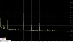
I remeasured now the 1kHz LP filter at the output of a cheap oscillator from ebay:
Low-distortion Audio-range Oscillator
using passive notch filter and an LNA.
I couldn't obtain the performance of this oscillator as it was then - I haven't touched it for more than three years, and I forgot the tweaks I made then. However, this is not very important now because the question was whether an active filter with an extremely linear op-amp can attenuate oscillator's higher harmonics without introducing additional distortion.
The spectrum shown on the first graph was obtained with an adjustable, Hall-topology passive notch filter (PCB by S. Groner), and an LNA by S. Wurcer (gain 60dB). The fundamental was at -6dBFS, so accounting for the notch filter gain at 3kHz (-6dB) and the LNA gain, the 3rd is at -98dBc.
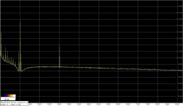
The second attachment shows the spectrum with the LP filter inserted between the oscillator output and the notch filter input. The 2nd harmonic is not visible, and the 3rd is attenuated by 22dB, as the theory predicts for the filter realization used.
The rest of the spectrum is clean, but the filter added about 10dB to the noise floor.
I tried also AD797 in the filter, but it seems to be oscillating at about 40MHz, so I must first take care of that.
So to the extent of my measurement setup, an LP filter at the oscillator output seems to attenuate higher harmonics without creating extra distortion, provided that the op-amp used has extremely low distortion.
Regards,
Braca
Low-distortion Audio-range Oscillator
using passive notch filter and an LNA.
I couldn't obtain the performance of this oscillator as it was then - I haven't touched it for more than three years, and I forgot the tweaks I made then. However, this is not very important now because the question was whether an active filter with an extremely linear op-amp can attenuate oscillator's higher harmonics without introducing additional distortion.
The spectrum shown on the first graph was obtained with an adjustable, Hall-topology passive notch filter (PCB by S. Groner), and an LNA by S. Wurcer (gain 60dB). The fundamental was at -6dBFS, so accounting for the notch filter gain at 3kHz (-6dB) and the LNA gain, the 3rd is at -98dBc.
The second attachment shows the spectrum with the LP filter inserted between the oscillator output and the notch filter input. The 2nd harmonic is not visible, and the 3rd is attenuated by 22dB, as the theory predicts for the filter realization used.
The rest of the spectrum is clean, but the filter added about 10dB to the noise floor.
I tried also AD797 in the filter, but it seems to be oscillating at about 40MHz, so I must first take care of that.
So to the extent of my measurement setup, an LP filter at the oscillator output seems to attenuate higher harmonics without creating extra distortion, provided that the op-amp used has extremely low distortion.
Regards,
Braca
Attachments
The Hall notch is only about -60 depth. Also with a buffer (X1) on the output, you have the distortion of the opamp as a follower. Low but could be better with a different topology.
THx-RNMarsh
THx-RNMarsh
The Hall notch is only about -60 depth. Also with a buffer (X1) on the output, you have the distortion of the opamp as a follower. Low but could be better with a different topology.
The output is minus the fundamental so the buffer op-amp distortion does not matter. The Hall notch has similar skirts since all these R/C notch filters rely on vectorial subtraction not resonance.
yes. two of them could be used to notch out residual 2H and 3H. For those contemplating using a low pass filter (LPF) to aid in removing harmonics.....
View attachment 1984_JAES_bonello_paper.pdf
and (file too large) ....
Active and Passive Elec. Comp., 1988, Vol. 13, pp. 113-132
Reprints available directly from the publisher
Photocopying permitted by license only
() 1988 Gordon and Breach, Science Publishers, Inc.
Printed in Great Britain
DISTORTION ANALYSIS OF ACTIVE
FILTERS
UMESH KUMAR and SUSHIL KUMAR SHUKLA
Department ofElectrical Engineering, Indian Institute of Technology,
Haus Khas, New Delhi-llO016, India
Centrefor Development of Telematics, Akbar Bhawan,
Chanakayapuri, New Delhi-llO021, India
(Received January 8, 1987, in finalform November 13, 1987)
These might be helpful in choosing the best topology with lowest distortion.
THx-RNMarsh
Last edited:
The output is minus the fundamental so the buffer op-amp distortion does not matter. The Hall notch has similar skirts since all these R/C notch filters rely on vectorial subtraction not resonance.
But Scott, I thought Braca inserted the opamp/LPF at the oscillator output, so would see the full output. No?
Jan
Correct, Jan.
The chain was oscillator => active LP filter => notch filter => LNA => sound card.
The filter topology I used has not been explicitly analyzed by Bonello, I merely followed the recommendation of Groner & Polak to use the inverting input of their composite op-amp, hence the Multiple Feedback Toplogy (MFB).
Can post the schematic if there is interest - no big deal, I used the old TI/BB filter design tool to match the resistor values to the capacitors I have in stock.
Regards,
Braca
Ahh you use the GP opamp, that explains a lot. Have you ever used it in non-inverting mode? That will invoke input CM distortion of course, but my measurements cannot detect input CM with lowish source R's. Only with large Rsrc (12k) I see some harmonics at around -140dBc.
Jan
Jan
As input source Z raises above zero, the non-linear input C is no longer effectively shorted to ground.
Complimentary parallel/push-pull inputs are inherently C cancelling topology and why I can use them even with low nfb and still get ultra low thd.
Its a characteristic of the CMA ability to have both high slew rate and very low distortion over wide BW.... by the cancelling of device C topology. It isnt a brute force approach of 250db nfb; its an alternative.
BTW
THx-RNMarsh
Last edited:
This is my first use of the GP op-amp.Ahh you use the GP opamp, that explains a lot. Have you ever used it in non-inverting mode? That will invoke input CM distortion of course, but my measurements cannot detect input CM with lowish source R's. Only with large Rsrc (12k) I see some harmonics at around -140dBc.
Jan
In the last paragraph on the left side of page 406 in the paper, G & P explicitly recommend using it in the inverting configuration, so the MFB topology seemed a logical choice.
Regards,
Braca
This is my first use of the GP op-amp.
In the last paragraph on the left side of page 406 in the paper, G & P explicitly recommend using it in the inverting configuration, so the MFB topology seemed a logical choice.
Regards,
Braca
Yes, absolutely. But it would be nice to have it in a non-inverting config so you can use it with high input impedance, so I made a proto board for it. Unfortunately, I can't reliably measure below -145dBc.
Jan
As input source Z raises above zero, the non-linear input C is no longer effectively shorted to ground.
Complimentary parallel/push-pull inputs are inherently C cancelling topology and why I can use them even with low nfb and still get ultra low thd.
Its a characteristic of the CMA ability to have both high slew rate and very low distortion over wide BW.... by the cancelling of device C topology. It isnt a brute force approach of 250db nfb; its an alternative.
BTW
THx-RNMarsh
A driven cascode also virtually eliminates common mode distortion in a non-inverting application. In one arrangement, the cascode bases are driven with a replica of the NFB signal. This is fairly straightforward in a flat-gain amplifier with a flat feedback network, but is less so if the feedback network is designed to be not flat. This also reduces the total effective capacitive load on the feedback node, which the parallel complementary approach does not.
Of course, a carefully bootstrapped cascode from the tail of the LTP also works in a similar fashion; the key here is to derive the bootstrapping signal with virtually no effect on the tail current.
Cheers,
Bob
- Home
- Design & Build
- Equipment & Tools
- Low-distortion Audio-range Oscillator