The question was whether low impedance gives better sound.
...for the reasons that were explained previously in this thread and where a valid comparison between drivers with solely different resistances requires the condition of having the same power input/output.
Lower speaker impedance merely puts more current load on amplifiers
...but requires less voltage headroom as a result. Using an appropriate amplifier is the key. Using an inappropriate amplifier moves the discussion instead to issues of problems with amplifiers.
This is largely due to the use of negative feedback to correct output voltage errors.
...which increases problems when clipping is possible. Not that I am an advocate of "no feedback amplifiers", just the right tools for the job.
One of the biggest reasons modern speakers are favouring 6 ohms --look around, lots of them out there-- is that it lets them use less copper in the voice coil, making for a smaller motor assembly.
When making a decision about voice coil resistance in a driver design, the VOLUME of the conductor (normally copper) is essentially a constant - unless there is a change in the design target. Coil resistance is a secondary consideration. There appears to be some confusion between sensitivity (per Watt) and voltage sensitivity.
The use of lower nominal impedances is a different subject to coil resistances since it includes the motional impedance and any efforts for conjugate load matching etc. in a crossover. It also concerns voltage sensitivity and there might also be a suspicion that manufacturers might prefer their loudspeakers sound slightly louder than others in a simple comparison - which then relies on the adverse effects of the amplifier loading not be an issue.
Last edited:
How do you know that the T/S parameters are the same? Because the datasheet states so? Those numbers "smells bad". I bet they differ in real world just as the Scan-Speaks or any other brand. Of course I may be wrong.On the other hand:
JBL 2226G Re=2.5 ohm Fs=40 Hz Qts=0.31 Vas=175.6 L
JBL 2226H Re=5 ohm Fs=40 Hz Qts=0.31 Vas=175.6 L
JBL 2226J Re=10 ohm Fs=40 Hz Qts=0.31 Vas=175.6 L
No difference!
Last edited:
If you don't trust a reputable manufacturer's statements, whom else do you trust at all? President Trump probably?
Best regards!
Best regards!
If you don't trust a reputable manufacturer's statements, whom else do you trust at all?
I guessed that was going to come.
Based on seeing hundreds of real measurement data or any other manufacturer's data, the data provided by JBL is pretty incredible. Even in one hundredth they are no different, sorry I don't eat that.
I bet the data of one model were copied to the others, we've seen like that from a "reputable" manufacturer before.
Anyway, trust the source you want, it's everyone's individual right.
Last edited:
If it was not for the fundamental resonance, then the driver would be a very inefficient sound radiator with a response rising at 6dB/octave rather than the nominal second-order high-pass response that gives a nominally flat pass-band.
Yes, for those who use huge values of equalization in order to keep the control of a heavy and large cone in a dipole configuration, the motor shoud be as powerfull as possible witin a restricted voltage range, therefore the impedance should be as low as possible. I'm doubting that there is a problem with such intensities since hypex modules are designed to handle an 1ohm motor.
IMHO, there is no reason to use another Q than the one that is requied for your application by the manufacturer and a flat response is always what we are looking for... what is the matter of lowering this Q?
...a flat response is always what we are looking for... what is the matter of lowering this Q?
A maximally flat response (in second-order case) requires Qts=1/sqrt(2) to give the second-order Butterworth alignment. Whilst this looks visually the most pleasing, it is not the most audibly benign roll-off. A second-order Bessel alignment where Qts=1/sqrt(3) offers lower group delay, which IMHO produces an audible benefit that is worth the slight reduction in output level when compared to the Butterworth alignment. But this is getting off-topic...
Not necessarily off-topic if we see the trend that lower impedance drivers produces lower Qes-Qts (except JBL haha), and roughly speaking, if we replace a BW aligned 8 Ohm driver with a 4 Ohm version, we may have a Bessel alignment from that point.A maximally flat response (in second-order case) requires Qts=1/sqrt(2) to give the second-order Butterworth alignment. Whilst this looks visually the most pleasing, it is not the most audibly benign roll-off. A second-order Bessel alignment where Qts=1/sqrt(3) offers lower group delay, which IMHO produces an audible benefit that is worth the slight reduction in output level when compared to the Butterworth alignment. But this is getting off-topic...
Last edited:
Because I have measured some ScanSpeak (and others) woofers, TS differ from declared but Qts difference is the same - lower Qts for 4-ohm models. I believe the same Qts difference is universal in majority of 4 vs 8 ohm drivers, notwithstanding some exceptions of the rule (JBL).How do you know that the T/S parameters are the same? Because the datasheet states so? Those numbers "smells bad". I bet they differ in real world just as the Scan-Speaks or any other brand. Of course I may be wrong.
Edit: If you are asking about JBL 2226, I don't know, but I have measured some other JBL models and they are spot-on with the declared TS parameters.
Last edited:
I referred to the JBL phenomenon only, which shows ecactly the same parameters for a 4-8-16 Ohm drivers, that is unbelievable.Because I have measured some ScanSpeak (and others) woofers, TS differ from declared but Qts difference is the same - lower Qts for 4-ohm models. I believe the same Qts difference is universal in majority of 4 vs 8 ohm drivers, notwithstanding some exceptions of the rule (JBL).
Not necessarily off-topic if we see the trend that lower impedance drivers produces lower Qes-Qts (other than JBL haha), and roughly speaking, if we replace a BW aligned 8 Ohm driver with a 4 Ohm version, we may have a Bessel alignment from that point.
For one special case you might find a driver with the right values of Qes and Qms to achieve that desire. But I still argue this is off-topic since we are talking about different final system alignments rather than the voice coil resistance. Certainly if you simply change one driver for another with a sole difference of driver resistance then you will get a different alignment. To compensate we might adopt a different Ft or redesign the driver to match the previous Qes (and Qms). But in both cases we are then comparing something other than the (non-)effect of the change in voice coil resistance. It might sound pedantic, but without such a qualification we will be in an eternal circle debating this! 🙂
A maximally flat response (in second-order case) requires Qts=1/sqrt(2) to give the second-order Butterworth alignment. Whilst this looks visually the most pleasing, it is not the most audibly benign roll-off. A second-order Bessel alignment where Qts=1/sqrt(3) offers lower group delay, which IMHO produces an audible benefit that is worth the slight reduction in output level when compared to the Butterworth alignment. But this is getting off-topic...
It depends a lot of the cut off frequency, as the energy requied by the motor IMO.
4 ohm versus 8 ohm is actually an interesting question, IMO. 🙂
Certainly commercial manufacturers have been doing the 4 ohm woofer bit for years.
IMO, because it sounds louder and brighter in the showroom face-off with the 8ohm jobbies, so most customers buy it. 🙄
4 ohms has its drawbacks, IMO. It needs bigger capacitors which tend to get pricey and huge in the MKP style. Electrolytics cost peanuts, so less of an issue. Coils are actually all about the same price however big you do them. Wire is cheap.
Also, cheaper amps, which can work well into 8 ohms, may struggle with 4 ohms.
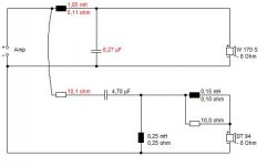
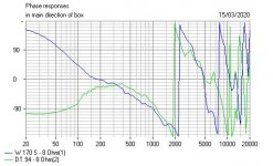
Anyhoo. I decided to sim a 6" woofer here in 4 and 8 ohm:
W 170 S - 4 Ohm | Visaton
W 170 S - 8 Ohm | Visaton
TaDa! Draw your own conclusions... 🙂
Certainly commercial manufacturers have been doing the 4 ohm woofer bit for years.
IMO, because it sounds louder and brighter in the showroom face-off with the 8ohm jobbies, so most customers buy it. 🙄
4 ohms has its drawbacks, IMO. It needs bigger capacitors which tend to get pricey and huge in the MKP style. Electrolytics cost peanuts, so less of an issue. Coils are actually all about the same price however big you do them. Wire is cheap.
Also, cheaper amps, which can work well into 8 ohms, may struggle with 4 ohms.
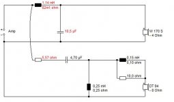
Anyhoo. I decided to sim a 6" woofer here in 4 and 8 ohm:
W 170 S - 4 Ohm | Visaton
W 170 S - 8 Ohm | Visaton
TaDa! Draw your own conclusions... 🙂
Attachments

It depends a lot of the cut off frequency, as the energy requied by the motor IMO.
If you refer to the audibility of the low frequency resonance, then no. But I am not sure of what point you are making, sorry?
...
Anyhoo. I decided to sim a 6" woofer here in 4 and 8 ohm:
W 170 S - 4 Ohm | Visaton
W 170 S - 8 Ohm | Visaton
TaDa! Draw your own conclusions... 🙂
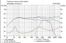
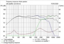
...evidently a simulation using a constant voltage source rather than the constant power source that would be required for an "apples to apples" comparison. Such a comparison would remove the 3dB difference in output levels.
My friend, there was no deception that I was simulating a constant-voltage source here. 🙂
Which is what the average Joe, like myself, owns.
Draw your own conclusions? I know 4 or 8 ohm is invariant on the guage, mathematically. 😎
If you wander down the main drag in Ryde, IOW, you will see this remarkable Pub Sign:

It looks like a mirror, but is actually a painting on a sphere.
It employs some very sophisticated Mathematics known as Conformal Geometry.
A flavour of it might be provided in this illustration which could be electromagnetism, the field around a coil, or an MTM speaker:
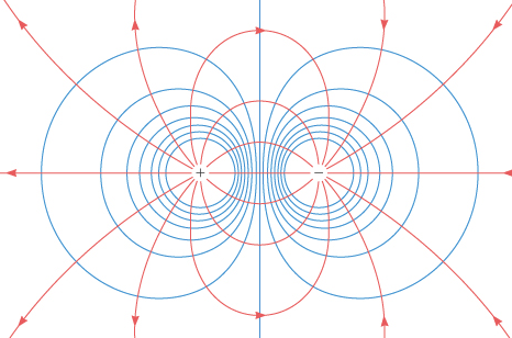
Angles are preserved.
All is Mathematics. 😀
Which is what the average Joe, like myself, owns.
Draw your own conclusions? I know 4 or 8 ohm is invariant on the guage, mathematically. 😎
If you wander down the main drag in Ryde, IOW, you will see this remarkable Pub Sign:
It looks like a mirror, but is actually a painting on a sphere.
It employs some very sophisticated Mathematics known as Conformal Geometry.
A flavour of it might be provided in this illustration which could be electromagnetism, the field around a coil, or an MTM speaker:
Angles are preserved.
All is Mathematics. 😀
If you refer to the audibility of the low frequency resonance, then no. But I am not sure of what point you are making, sorry?
The audibe aera of acoustic energy under the cutoff frequency is highly dependant of the slope, there will be a lot more energy with a 6dB/oct slope one than a 12dB/oct one. And the acoustic energy requied for the 6dB slope is supperior, even if the frequency response graphical representation have the same aera.
The audibe aera of acoustic energy under the cutoff frequency is highly dependant of the slope, there will be a lot more energy with a 6dB/oct slope one than a 12dB/oct one. And the acoustic energy requied for the 6dB slope is supperior, even if the frequency response graphical representation have the same aera.
I still have no idea what this has to do with anything in this thread? But defining Qts for a first-order 6dB/octave slope provides an interesting challenge. Ultimately low frequency output is displacement limited too, which tends to reduce the output feasible at 6dB/octave to less than that at 12dB/octave.
It seems to me that what determines the drive is the number of electrons flowing, and this can be from a lot in a larger conductor in a 4 ohm driver, or fewer in a smaller wire of which there are more turns - an 8 ohm driver.
The tendency to assume that what is visually better looking on a graph is necessarily also necessarily better to the ear has concerned me for a while; they are different ways of accessing truth, but the ear is what we are designing for, not the visual perception, (aesthetic perhaps), of the eye.
The BW alignment has a compromised transient performance, and lower rates of roll off, (6dB/oct), align better with the need for matching room reinforcement needs.
It seems to me that what determines the drive is the number of electrons flowing, and this can be from a lot in a larger conductor in a 4 ohm driver, or fewer in a smaller wire of which there are more turns - an 8 ohm driver.
It might be a way to describe the input signal, but what is important is the transfer of energy which is what the concept of impedance enables us to discuss. And in that context, the coil resistance is an irrelevance.
The BW alignment has a compromised transient performance, and lower rates of roll off, (6dB/oct), align better with the need for matching room reinforcement needs.
Simply lowering Qts ameliorates the compromise in transient performance due to a Butterworth alignment. Lowering the roll-off rate instead simply means having to curtail the low frequency output demanded by a first order roll-off - whether that be electronically synthesised or generated from a dipole (which tends in-room (rather than free space) to a second order 12dB/octave roll-off in any case).
I still have no idea what this has to do with anything in this thread?.
Sorry, i go out

But the ideas are like the conductance, it is a ballistic displacement.
- Home
- Loudspeakers
- Multi-Way
- Low impedance = better sound?