Hello guys, Imlooking for a good single ended EL84 schematic. I will be happy with bigger power. All my audio projects I worked with were single ended triodes which puts out 2watts maximum. And now I want to try something different.
I have 5k output transformers made for el84 in pentode. My plan is using pentode mode and local feedback including the output transformer so it will have better frequency response.
But where actually start? I have never worked with pentodes.
How to properly implement the feedback?
Sorry for these newbie questions. Thanks much for any reply.
Best regards, Michal
Try the RH84.
There are single ended triodes that will make significantly more power than 2W. EL84 SE pentode wired will be 4-6W.
There are single ended triodes that will make significantly more power than 2W. EL84 SE pentode wired will be 4-6W.
Try the RH84.
There are single ended triodes that will make significantly more power than 2W. EL84 SE pentode wired will be 4-6W.
A surprising project.
I did it in point-to-point style, then I designed a pcb for it. It needs good quality output transformers and generous section even if the power is low.
RH84 gets some flak around these parts at times, but I built one as published several years ago and it was a nice single-ended amplifier IMO.
If you're interested in feedback schemes, it's certainly something to play with. Sticking a pentode in the front end (for an all pentode amp) would actually make the feedback more effective, too. I'm bet there's a modified version of the schematic somewhere that does this with a 6AU6 or something.
If you're interested in feedback schemes, it's certainly something to play with. Sticking a pentode in the front end (for an all pentode amp) would actually make the feedback more effective, too. I'm bet there's a modified version of the schematic somewhere that does this with a 6AU6 or something.
We liked our RH84 derivatives. It is hard to make a bad EL84 amp. My favorite is far is a class A PP triode with 3.9 w output at clipping. Based on Scott iron.
dave
dave
Agreed 100%. I've always wondered how much of that flak was due to the acrimony incubated by the original thread, and how much was generated by the DHT purists. We may never know - and honestly, I'm not even sure it really matters; we're all entitled to our opinions.RH84 gets some flak around these parts at times, but I built one as published several years ago and it was a nice single-ended amplifier IMO.
I built one during the early days of that thread just to see what all of the hubbub was about and it wound up being my primary amp for a good seven or eight years. I rebuilt it in November 2017 and dragged it to Burning Amp where it was warmly welcomed. But I'll have to admit that I was a bit embarrassed to tell anyone what it was because of its checkered history on the forum.
I've said it before: the RH84 is what it is. If you're looking for Macintosh-like distortion figures, thundering bass or for the "soundstage" (jeepers creepers 🙄) of a DHT, then look elsewhere. But if you're looking to satisfy the itch to build, it's a hard one to beat. Extremely low parts count, quick to build, cheap as chips, responsive to using good parts, and sounds decent to boot. What's not to like? 🙂
Last edited:

Dave Gillespie
Magnavox Flea Power: Getting More Out Of The 8600 Series - A Lot More! | Audiokarma Home Audio Stereo Discussion Forums
says, 3.65 watts RMS, +/- 0.5 dB, 25-40 kHz
schematic is on page 6, uses very inexpensive output transformors (I tried to post the schematic -didn't work)
AES PT-31
Transformer - Output, 8 W, Single Ended | Antique Electronic Supply
Decware
ZKIT2 / Zen Triode SET multi channel tube amplifier kit
Last edited:
To Planet-10: Care to share a schematic of your favourite
Dave
Care to share with us a schematic of your favourite EL84 PP Class A triode amp with Scott iron.
Dave
Care to share with us a schematic of your favourite EL84 PP Class A triode amp with Scott iron.
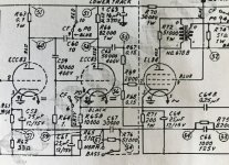
...schematic is on page 6...
A fairly straightforward design. Do note the PS where he has done a good job. I am not a big fan of 12AX7 up front, Eli Dutton uses the !2AT7 as it has transfer curves that work with the EL84 transfer function to give a more linear amplifier.
It also has a standard feedback scheme, i prefer the Schade feedback used in the RH84. We ended up using EF86 in triode, things like 6DJ7 variants and other front ends can be used, the EL84 is easy to drive.
Decware
After having a couple of Decware amps thru here it is hard to get excited by them.
dave
Attachments
Another example is that used in the Tandberg 74B reel-to-reel, also TB5.
I’d guess this one has way too much gain in front, no need for 2 12AX7 stages.
dave
Care to share with us a schematic of your favourite EL84 PP Class A triode amp with Scott iron.
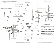
The amp is based on El Cheapo (many threads on El Cheapo) with the EL84 strapped into triode, the power supply adapted to the Scott PS, and the front end reg used was the same as those from Bottlehead and in the Jones tome.. I do not have a schematic for it, but here is El Cheapo.
CCS:
dave
Attachments

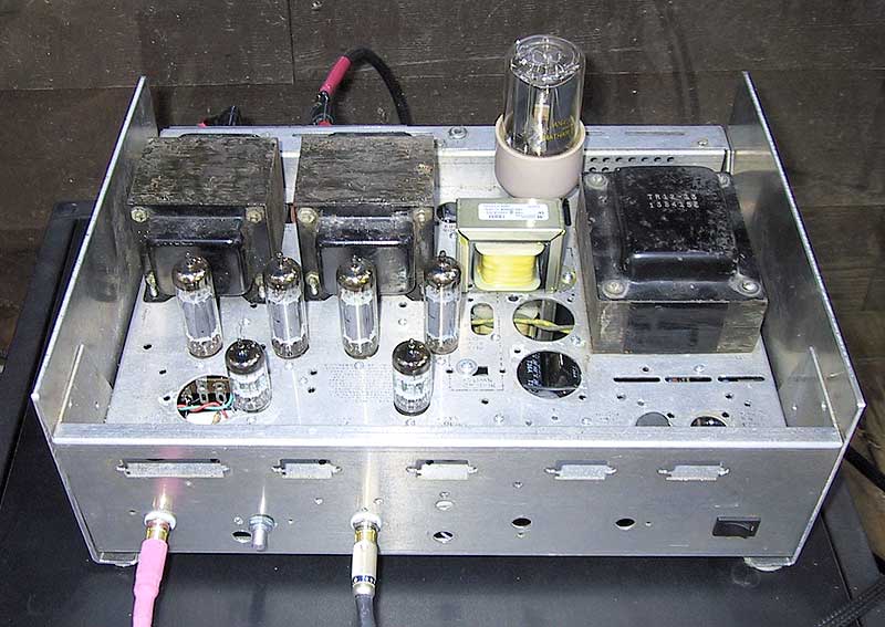
From DIYtube the Budgie that I built nearly 7 years ago. At the moment working on a replacement optimized for the ProAc Tablette 10 (sealed enclosure, 10 Ohm impedance).
I've used the Ayumi model for the 6BQ5. A model for the 2C51 shows hardly any difference with the WE396A. Rk can be increased to 260 Ohm but then the 8 Ohm performance deteriorates.
For tube alternatives I'll be using: WE386A / 2C51 / 5670 / 6N3P-E / 6N3P-EV and the EL84 / 6P14P-EV / 6P14P-ER.
Transformers are Transcendar TT-234-OT with 22.5% tap for UL.
Picture is of the Budgie
Attachments

Last edited:
AmadeusMozart,
Nice looking amp!
And a good straightforward schematic.
I like it.
But I am curious about your wattage ratings.
You show the highest output as being 1.54V pp (peak to peak?)
(V peak to peak) / 2.828 = Vrms
1.54/2.828 = 0.545Vrms. Too low to be powerful into 10 Ohms.
Instead, did you perhaps mean 15.4V peak to peak?
15.4Vpp/2.828 = 5.45Vrms
(Vrms)squared / Ohms = Watts rms
(5.45Vrms)squared / 10 Ohms = about 2.97 Watts to 3 places
That seems more like it.
I have lots of different speakers, including Tablette Signature 2000, and have driven them from 1 - 2 Watt amplifiers, and of course higher power too.
Yes?
Also, move R8, and put it directly on the 396 grid and the other side of R13; that way R8 becomes a true grid stopper. And the rest of the circuit will perform 99.9% exactly as before (in all practicality exactly as before moving R8). WE396A are RF capable tubes, grid stoppers are good for audio.
Keep listening to that amp and those tablettes.
Last edited:
The amp in post 10 is a nice amp. With about $100 in transformers and choke the rest of the parts you might have around.......... easy to build.
AmadeusMozart,
Nice looking amp!
And a good straightforward schematic.
I like it.
But I am curious about your wattage ratings.
You show the highest output as being 1.54V pp (peak to peak?)
(V peak to peak) / 2.828 = Vrms
1.54/2.828 = 0.545Vrms. Too low to be powerful into 10 Ohms.
Instead, did you perhaps mean 15.4V peak to peak?
15.4Vpp/2.828 = 5.45Vrms
(Vrms)squared / Ohms = Watts rms
(5.45Vrms)squared / 10 Ohms = about 2.97 Watts to 3 places
That seems more like it.
I have lots of different speakers, including Tablette Signature 2000, and have driven them from 1 - 2 Watt amplifiers, and of course higher power too.
Yes?
Also, move R8, and put it directly on the 396 grid and the other side of R13; that way R8 becomes a true grid stopper. And the rest of the circuit will perform 99.9% exactly as before (in all practicality exactly as before moving R8). WE396A are RF capable tubes, grid stoppers are good for audio.
Keep listening to that amp and those tablettes.
Those were the input voltages.
You are correct on a grid stopper on the 396A, I just copied another schematic and I modified it, did not pay too much attention to the input.
Although I have made a mistake in modelling the UL output transformer according to post 17 in this thread: Modeling Pull-Push transformer in LTspice
Values for the OPT are: L1 = 1.2H, L2 = 19.2H, L3 = 0.048H. Remainder stays the same. Depending on whose model for the 6BQ5 you use you'll get something like 3.2Watt to 4.1Watt. Suspect this is due to the different manufacturers have slightly different tube characteristics. Optimum output seems to be around the 10 - 11 Ohm speakers due to using a 5000 : 8 Ohm OPT and in UL you'll want a tad higher imedance than 5000.
It will allow me to use the Tablette but there are also many speakers that are around the 6 Ohm which I can happily connect to the 4 Ohm tap.
I was taught that if a transformer is bobbin wound then use a small capacitor of 5nF in series with a 22K 1W resistor over the primary of the OPT to stop the ringing. Unfortunately there are not many that still wind output transformers properly and if they do then they are expensive. I bought some Hashimoto and they were not bifilar woud, was quite disappointed with those. VVT in the UK still makes decent ones as far as I am aware but costly. Valve Audio Amplifier Output Transformers for Push Pull circuits
When hard wiring you might sometimes encounter some instability around the EL84 and grid stoppers together with a small capacitor of 50 - 100pF from g1 to ground will stop that.
Someone once said "I've have not heard a bad EL84" and I think that is true when properly build and halfway decent iron is used. When using cheap iron you better look at Schade feedback (RH84).
To the OP: I suggest to play around in LtSpice with a model, you'll learn heaps and get close to the final result. Quality output transformers are important and do not undersize the mains transformer (what many do). (Hammond has a page on their website on how to do this)
Attachments
Last edited:
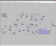
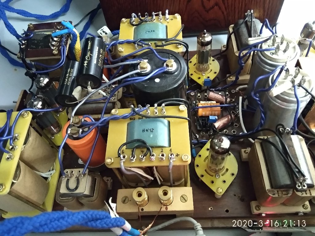
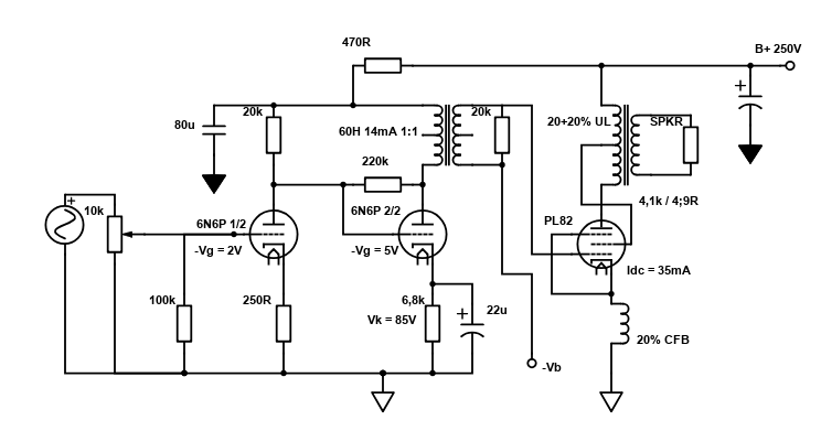
I highly recommend trying a CFB SE amplifier. It retains a lot of SE magic (immediacy and intimacy), while having clean, punchy bass and lacks that typical high level SE distortion most amplifiers do (for good).
The DF of this current prototype amplifier is 7,8. I can even go higher if needed.
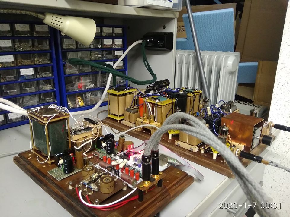
This prototype board to the far right is built with a PL82 tube.
The power supply is single transformer, tube rectified with PY82, then LC (split) LC.
Thanks to Mr. Patrick Turner, there's a lot of useful info of CFB + UL amplifiers on his website.
The DF of this current prototype amplifier is 7,8. I can even go higher if needed.
This prototype board to the far right is built with a PL82 tube.
The power supply is single transformer, tube rectified with PY82, then LC (split) LC.
Thanks to Mr. Patrick Turner, there's a lot of useful info of CFB + UL amplifiers on his website.
Last edited:
AmadeusMozart,
Bifilar transformers are 1:1. You get the same input and output impedance.
Bifilar means the two wires are side by side for the complete length of the wire (all turns are side by side, to make it essentially unity coupled).
A good example in audio is a 1:1 interstage transformer.
Perhaps you meant unity coupling audio transformers that use bifilar windings, the plate and cathode wire pair are wound side by side.
Sounds like something done by McIntosh and perhaps a Fisher model or two.
Unity coupled plate and cathode requires Extremely high voltage swing from the driver.
In push pull outputs, that is often done by cross-wire connecting the top of the driver plate loads to the output plates (Positive feedback). In solid state, this is called bootstrapping.
In single ended, there is no way to cross wire the driver load to the other output stage, there is only one phase of SE output.
But Global negative feedback needs to wrap around these stages to get the distortion back down (compensate for the positive feedback).
It is interesting that in order to use the local negative feedback of unity plate cathode coupling to get distortion reduced, the circuit also uses positive feedback to the driver stage to get the extra required driver voltage swing, which increases the distortion.
No free lunch.
For RF applications, the windings can be connected in series as a 2:1 autoformer (4:1 impedance ratio).
I have not seen Bifilar used this way in audio. Wiring in series with lots of turns has problems because of the distributed capacitance.
Some RF bifilar, trifilar, and quadrifilar transformers only use 2, 3, or 4 turns.
There are ways to have trifilar windings and quadrifilar windings for RF applications.
In RF the impedance ratios are 9:1 and 16:1.
Forget this for audio.
Last edited:
AmadeusMozart,
.....
If done properly in push pull both the windings for the primary are wound bifilair, if voltage insulation required is higher than can be offered then it will be alternative layers for the primary winding and not bobbin wound. The Williams amplifier was very sensitive to the construction of the output transformer, if it was not just right then the whole amplifier was unstable.
In any case the DC resistance should be rather close and the voltage drop across the two primary windings can be used to balance the current through the power valves (if so inclined with the high voltages involved) since the grid current can be quite different for tetrodes and then measuring the cathode current is greatly misleading. I have never before noticed such a large difference in dc resistance as with the Hashimoto PP output transformers. We are not talking a few percent at most, no, it was in the order of 20% or 30%. Forgot exactly how much but it was no use to measure the voltage across the windings.
As ex-HAM I know enough about building tube and RF power transmitters, heck it may have even laid the foundation for the collapse of my immune system since the T-cells in the blood are sensitive to RF.
Last edited:
- Home
- Amplifiers
- Tubes / Valves
- Best EL84 SE amplifier?