1% THD is, ahem, mediocre, easy to hear spurious harmonics of a sine wave, very obvious intermod, basically not high fidelity at all. Quite obvious on an ABX test. Good enough
for speech of course, as is 8 bit audio come to that.
for speech of course, as is 8 bit audio come to that.
aboos - not sure which design you were thinking of. The JLH as at the start of this thread works in push pull as Nico showed.
The Aleph 4 also - through a novel circuit - drives its FETs in anti-phase. But if anyone has designed a single ended class A it will be Nelson Pass.
You were probably thinking that the PNP current source was a constant current to the upper OP tranny. It is only a CCS to the VAS stage. THe driver transistor still sucks current out of the top O/P device when it wants to.
Neither of the articles that I have read have explained what the two pot's do and how to set them?
RV1 sets the bias current of the lower half amplifying stage Tr3-Tr1.
RV2 sets the bias current of the upper half current source combo Tr5-Tr2.
Should be set to equal values obviously, but as pointed out by Osvaldo in #29, there's no temp-control in this design; and with two adjusting pots, it is prone to destabilisation in time.
And adding two independant temp-control circuits (for the upper and lower half sections), risk of temp-oscillation is very possible (second order equation). Such extras to have this amp a&t-stable (one half current steady, the other to stabilize; one half amplifying, the other perfect passive) will change the design dramatically.
Mars's response reminded me that no-one had answered that question before!
The purpose of RV1 is primarily to set the output rail to zero volts. But the two controls are not independent, unfortunately. That means changing one affects the other. And preferably using two meters, one connected between the output rail and ground and the other across the 0.33 ohm current sense resistor (both measuring volts), to see the effects simultaneously.
RV2 controls the overall bias current in the OPS. The current setting needs to be high. On further investigation into the behaviour of the upper CFP (PNP/NPN) they neither form a true CCS for the lower O/P stage nor a true CCS for the driver transistor. As a result the upper O/P device does work in anti-phase to the lower, as described previously, but modulation in the PNP current means the NPN has a reduced current swing. The optimum is best set up with the aid of an oscilloscope and/or distortion analyser I suspect.
In fact because of this partial mid-way between a fully push pull and a CCS loaded amplifier, I suspect that the distortion is going to be higher than in the original. I would have thought a true CCS for the driver would have been a better solution.
Perhaps someone will design a DC servo to control the Iq and OP rail voltage in these amps - even using a microprocessor, as I think I would if I were to design one.
Setting to 1.5A should be adequate. If you don't have two meters then you will have to alternate between measuring current (that is, the voltage across the 0.33 ohm) and the output voltage (not forgetting to change ranges if your meter is manual/analogue).
If JLH wanted to provide a true CCS to the driver stage, the capacitor attached to the base of the PNP would have been connected to the positive rail and the base biased from a low impedance source (i.e. no series resistor). As it is connected to the emitter, it behaves partially as a gyrator but with a current ripple dependent on the 0.33 and 3.3k base resistor. Which seems to be a similar idea in the Aleph 4 too.
Perhaps I can also repeat my earlier comments in another thread that the JLH suffers a poor slew rate in the upward edge of a square wave, asymmetrical with the down edge especially if older hometaxial base transistors are used. If still using these it would be an improvement to swap them for a newer, at least 4MHz device, if not the faster 30MHz-ish devices like the MJL3281A. That would give the amplifier at least a chance of competing with a MOSFET in frequency response. THough it may need a small frequency compensation capacitor added for stability.
That would be Mars' (without the extra s)Mars's response...
That's another way to say the same. As the upper half current source is set with RV2, it is desirable to have the output at zero volt by adjusting RV1 until the lower amplificating half is sinking the exact same amount of (bias-) current.The purpose of RV1 is primarily to set the output rail to zero volts.
A μP???Perhaps someone will design a DC servo to control the Iq and OP rail voltage in these amps - even using a microprocessor.
An opamp, one input at ground, the other sensing the output dc (through RC filter), output adjusting the upper half current source (add series resistor here). DC loop control should be inverting.
Formal English allows two s's to be used. That's a little pedantic, but there we are.That would be Mars' (without the extra s)
But I agree with your other comments.
>>Mars' (without the extra s)
> Formal English allows two s's
First rule of Strunk & White:
Elementary Rules of Usage
1. Form the possessive singular of nouns by adding 's.
Follow this rule whatever the final consonant. Thus write,
Charles's friend
Burns's poems
the witch's malice
Exceptions are the possessives of ancient proper names ending in -es and -is, the possessive Jesus', and such forms as for conscience' sake, for righteousness' sake. But such forms as Moses' Laws, Isis' temple are commonly replaced by
the laws of Moses
the temple of Isis
The pronominal possessives hers, its, theirs, yours, and ours have no apostrophe. Indefinite pronouns, however, use the apostrophe to show possession.
one's rights
somebody else's umbrella
A common error is to write it's for its, or vice versa. The first is a contraction, meaning "it is." The second is a possessive.
It's a wise dog that scratches its own fleas.
Rule 2, commas in lists, can really start a fight.
If anyone is following my build, there were a few mistakes in the PCB layout which were easily sorted.
However, the biggest problem is that the legs of the BD139/BD140 transistors are stretched to their limits. Ideally their pads need to be closer to the mounting holes.
However, the biggest problem is that the legs of the BD139/BD140 transistors are stretched to their limits. Ideally their pads need to be closer to the mounting holes.
I'm quite surprised by the heatsink requirements of this simple amp. My Aleph 4 runs 100W but uses less heatsink area ?
The Aleph 4 spec. is also a huge 1% THD, though that may be a nominal figure to indicate that it doesn't pretend to be a hi-fi design.
The spec says 1% THD @ 100W. One definition for max power often used is the power when THD reaches 1%. Since the Aleph 4 is specified at 100W the 1% figure tells you nothing att all, right?
Quite right, specifying 1% or 0.1% at the limit tells little about the overall distortion performance of an amplifier.
Many amplifiers would also specify THD at 1W and half power as well. But for class A where they really shine (vs. class AB) is in the very low output (sub 1W) as there is no crossover distortion to contend with and this tends to be in the very linear portion of the transistor (or tube) operating envelope.
Many amplifiers would also specify THD at 1W and half power as well. But for class A where they really shine (vs. class AB) is in the very low output (sub 1W) as there is no crossover distortion to contend with and this tends to be in the very linear portion of the transistor (or tube) operating envelope.
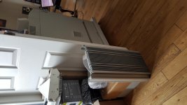
Do you have a washing machine in your living room?...LED light fittings that ... are enormous
They are moderate large, but such surface demands proper heat transport, often realised by a solid and thick bottom. These are meager however. Cast to fit the appliance I think. Have the heat sources distributed well over the area.
So in english it is mandatory to use ~s's, whereas in my own tongue it is erroneous. So Mars's instead of Mars' but if I had adopted Mares it would be Mares'! What about Bravo: Bravo's, Bravos or Bravoos?...really start a fight.
Nope, British English is as follows " Jacques' books were arranged biggest to smallest" meaning "the books of Jacques." That's (that is) the correct way. Point. No discussion.
The rule is that if the word (plural or not) ends with an "s" then an apostrophe is placed immediately behind the "s" and is pronounced as if there were an 's.
Kevin
See below
The apostrophe
The rule is that if the word (plural or not) ends with an "s" then an apostrophe is placed immediately behind the "s" and is pronounced as if there were an 's.
Kevin
See below
The apostrophe
Last edited:
The original heatsinks were OK but the dumpster sinks are easier to incorporate into a design for an enclosure.
Do you have a washing machine in your living room?
They are moderate large, but such surface demands proper heat transport, often realised by a solid and thick bottom. These are meager however. Cast to fit the appliance I think. Have the heat sources distributed well over the area.
So in english it is mandatory to use ~s's, whereas in my own tongue it is erroneous. So Mars's instead of Mars' but if I had adopted Mares it would be Mares'! What about Bravo: Bravo's, Bravos or Bravoos?
I think it is very unfair to criticise people whose first language isn't English.
Thanks's!I think it is very unfair to criticise people whose first language isn't English.

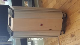
I'm going with the bigger salvaged heatsinks as it is easier to incorporate them into a DIY cabinet design. The heatsink profile allows for a simple wooden box to fit between the heatsinks.
Last edited:
I'm just collecting the parts together to try the Pass Aleph J.
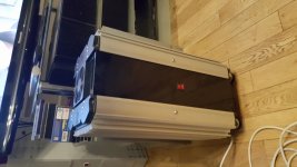
I'm quite pleased with the case that I built with the scrap heatsinks.
I'm quite pleased with the case that I built with the scrap heatsinks.
Attachments
Last edited:
Since that photo the wood is now piano black and looks really smart.
Attachments
Last edited:
- Home
- Amplifiers
- Solid State
- 25W Class A Amplifier