So shall we call it rails and profiles then? It would be good to know what we are talking about. I can't help with that. I don't use rails with loft (so far).
- This is the version with separate files option: ath-4.4.3-beta-4.zip
Use something like this:
Out.CoordFiles.NumProfiles = 8
Out.CoordFiles.Delimiter = " "
Out.CoordFiles.SeparateFiles = true
- This is the version with separate files option: ath-4.4.3-beta-4.zip
Use something like this:
Out.CoordFiles.NumProfiles = 8
Out.CoordFiles.Delimiter = " "
Out.CoordFiles.SeparateFiles = true
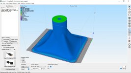
Without rails I could create surf loft and export STEP file to Solidworks. Output files extension for Solidworks is txt.
Attachments
Last edited:
I tried your project and it's strange - with SurfaceImport it creates only the first 15 sketches (and fails), even though when imported without lofting, it works fine. That may be hard to debug...
Attachments
Last edited:
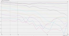
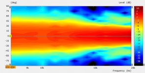
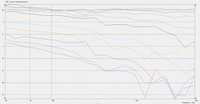
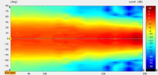
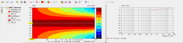
M2 ish 8K to 20K ABEC result
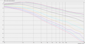
For what it is worth here are the VACS graphs for running the M2 style waveguide between 8K and 20K, looks quite good overall driven by a perfect radiator.
For what it is worth here are the VACS graphs for running the M2 style waveguide between 8K and 20K, looks quite good overall driven by a perfect radiator.
Attachments
When I try to add the new lines in the configuration files I get a syntax error, I copied the lines from the readme so I'm not sure what I'm doing wrong😕 Tried with both of the betas, I put the exe in the same folder I was using before to run the tool as the betas are called ath.exe so they should be able to coexist?
I tried 8 and 4 as the number of profiles with the same error.
I tried 8 and 4 as the number of profiles with the same error.
Attachments
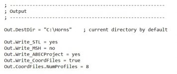
This config worked (not sure why having the other lines in but commented out made it work) but I could not get the separate profiles to work without a syntax error. Surface loft in Fusion then worked
Code:
 ; -------------------------------------------------------
  ; Output
  ; -------------------------------------------------------

  Out.DestDir = "C:\Horns"    ; current directory by default

  Out.Write_STL = yes
  Out.Write_MSH = no
  Out.Write_ABECProject = yes
  Out.Write_CoordFiles = true
  Out.CoordFiles.NumProfiles = 8
  ;Out.CoordFiles.Delimiter = " "
  ;Out.CoordFiles.SeparateFiles = true
Attachments
Last edited:
That's fine if you like the beaming. I don't.
The README file is in the zip archive (the link).
There's only one file in the zip archive, named "ath.exe"
I tried extracting the ath.exe file and it spit out these:
.bss
.CRT
.data
.idata
.pdata
.rdata
.text
.tls
.xdata
But each one of those appears to be a binary of some sort.
Is anyone else finding a zip file inside that archive? I'm on Windows 10.
The readme is in the version 3 beta zip not the version 4
Attached here, you''ll need the version 3 zip for the Fusion add ins though.
Attached here, you''ll need the version 3 zip for the Fusion add ins though.
Attachments
Last edited:
The Fusion add-ins read one single file, semicolon separated values. So for Fusion you have to keep the settings default:
Out.Write_CoordFiles = true
;Out.CoordFiles.Delimiter = " " <--- set it to ";" for Fusion 360 (or don't specify at all)
;Out.CoordFiles.SeparateFiles = true <--- set it to false for Fusion 360 (or don't specify at all)
Out.Write_CoordFiles = true
;Out.CoordFiles.Delimiter = " " <--- set it to ";" for Fusion 360 (or don't specify at all)
;Out.CoordFiles.SeparateFiles = true <--- set it to false for Fusion 360 (or don't specify at all)
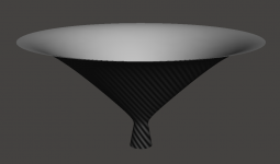
Throat conical extension - beta 5
I've always wanted to know what happens for a conical throat extension. Now you can try it yourself:
ThroatExtension = 20 ; [mm] (default = 0)
Download link: ath-4.4.3-beta-5.zip
I've always wanted to know what happens for a conical throat extension. Now you can try it yourself:
ThroatExtension = 20 ; [mm] (default = 0)
Download link: ath-4.4.3-beta-5.zip
Attachments
The Fusion add-ins read one single file, semicolon separated values. So for Fusion you have to keep the settings default:
Out.Write_CoordFiles = true
;Out.CoordFiles.Delimiter = " " <--- set it to ";" for Fusion 360 (or don't specify at all)
;Out.CoordFiles.SeparateFiles = true <--- set it to false for Fusion 360 (or don't specify at all)
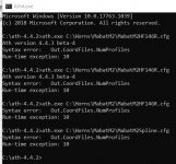
What is weird for me is that I had to specify them commented out for the configuration to run, if I left them out entirely I got a syntax error. The attached cmd screen shows the errors with the code on the right that caused them, the last one went through no problems. Maybe that doesn't happen for anybody else, it works for me with those settings so I just thought I would report it in case anyone else gets the same.
Attachments
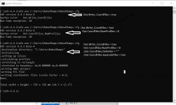
I reproduced the error. It happens when one single empty line is present at the end of the file. I will fix it. For now just enter one more empty line there, or no at all.
Hi, this is fun tool!
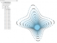
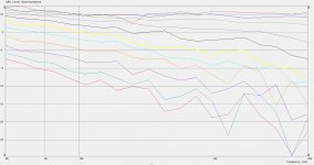
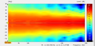
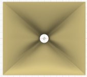
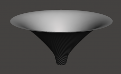
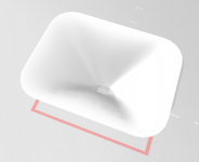
Not sure what I'm after just playing around. Got some smooth looking diagonal response, is there a way to extract the profile from the "corner" or some other tips how to get the performance to the horizontal axis?😀
Also, any tips how to get a wave guide larger? I tried to tune the depth and / or variables of the super formula but the performance gets nowhere near. By good performance I think the lines in the SPL graph should be smooth and not overlap?🙂 Thanks!
Attachments
Last edited:
Make it round 🙂Got some smooth looking diagonal response, is there a way to extract the profile from the "corner" or some other tips how to get the performance to the horizontal axis?😀
For the corner profile, import the file *_profiles.csv with Ath4_CurvesImport add-in and make sure you set Out.CoordFiles.NumProfiles = 8 (that includes the diagonals).
gedlee
Re PWT, I'm not sure you mentioned this before - what about a (typical) conical exit of a compression driver connected directly to a straight duct? Wouldn't that deteriorate the results? I will have two tubes, ⌀1" and ⌀1.5" - would a smooth transition insert from 1" to 1.5" make sense for 1" drivers? These could be printed easily, I guess.
The exit angle issue is a complex one. The technique will give you the actual shape of the exit waveform, so in that sense it is not incorrect. But doing this may take some high resolution and the ability to run the algorithm with evanescent waves. In any case, the errors will be less than what I would expect to be the non-ideal exit waveform of most drivers. What one wants to know is how close is the drivers exit wave conform to what the waveguide expects.
I would not use a conical flare - use two different size tubes. The conical flare that is not actually part of the driver itself would likely cause substantial errors.
I was gone to Spain for the last week.
Thanks.
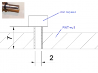
Preparing the PWT mics, there's a possibility to make a very small narrow tube extension as a pressure probe (see the drawing; [mm]). Would that make sense? Wouldn't it disrupt the sound field inside the tube too much? Plenty of such holes could be prepared in various places in the tube, plugged if not used. Some form of mics calibration will be necessary anyway.
Preparing the PWT mics, there's a possibility to make a very small narrow tube extension as a pressure probe (see the drawing; [mm]). Would that make sense? Wouldn't it disrupt the sound field inside the tube too much? Plenty of such holes could be prepared in various places in the tube, plugged if not used. Some form of mics calibration will be necessary anyway.
Attachments
Last edited:
I think that not having the microphones flush mounted will cause lots of problems. The tube extensions will act as resonators/filters and any vacant ports must be flush (even if closed.) The extension may not be so bad on a single mic, but still the response would have to be adjusted (just how is a big question.)
OK, I won't complicate it, I suspected it could cause trouble. I'll flush mount all the capsules.
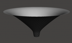
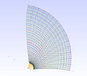
In the meantime, I'm working on a spherical wave source (or vibrating cap, alternatively) and mesh construction redesing - this will be a major update. A lot simpler and better now - some ideas come after a long time.
In the meantime, I'm working on a spherical wave source (or vibrating cap, alternatively) and mesh construction redesing - this will be a major update. A lot simpler and better now - some ideas come after a long time.
Attachments
Last edited:
- Home
- Loudspeakers
- Multi-Way
- Acoustic Horn Design – The Easy Way (Ath4)