That's all very much within the realm of phono MM indeed, so my hunch was correct. Any clue about levels at this stage?I am struggling with that also---my best guess, from Nortronics head brochures, is about 4K impedance, and 650Ω resistance. [at 1 kHz // edit]
That's certainly possible, but I suspect it may be creating more problems than it's worth. I would definitely want to fire up LTspice and simulate the thing as-is to get an idea of its performance; an LM318 SPICE model does appear to be available.Definitely true there---I'm thinking that tape noise/distortion overrides any electronic contribution as well; I'm just wondering if a small NPN/680Ω wrapped around the 2N3964 would be slightly better, due to Rod's comment about the CFP combination being more linear than any single transistor.
Again, first check out whether it is even needed at all.That's about what I was thinking, and that SUCKS. I'm gonna run the line input around the mic pre---I don't think it will be too messy; we'll see.
AES48-2005 in a nutshell: Pin 1 goes to Chassis ground as directly as possible.Hmmmmm....not exactly following you there. I was gonna put in a ground bus bar ala the "Star Grounding" technique alluded to earlier. Maybe I should just connect all the pin 1s to there.
The point is basically having any shield currents go around the whole circuit on chassis rather than making their way to central star ground via local circuit ground, which would generate a finite voltage drop over your signal ground return where you don't want it. This would effectively degrade input CMRR. People used to be wondering why they would be getting ground loop issues among pro gear despite balanced interconnects, so yes, this can very much be a real-life issue, especially in gear with less than oversized ground traces.
(It might make more sense if you consider components that are connected to PE, i.e. IEC Class I. You want ground loop currents to be traveling PE device 1 --> chassis --> cable shield --> chassis device 2 --> PE device 2 without any detours over signal ground returns in between.)
For obvious reasons, chassis ground has to connect to circuit ground somewhere for shielding to be effective, I just don't know where the designated spot for that would be in this case. The input panel would certainly be attractive (it would keep RF out of that section), but maybe there's a connection in the power supply section already.
Any other connections of signal ground to chassis ground would be at RF only, via maybe a few nF ceramic where needed. This RF bonding should do a decent job at keeping RF out.
I don't think there's a whole lot to gain - aren't these the output drivers with their 22k and 100k resistors anyway? LM4562s are only going to be more noisy under these conditions (as you should find out if you plug in their voltage and current noise densities with these part values - I'm getting about 4 dB more output noise), and NE5532s are fine line drivers as-is.Now the only thing remaining is the bus drivers---which are currently NE5532s, which really are fine ICs for the most part. I could also replace those with LM4562s, which are quieter, cleaner, and faster; but the NE5532s have MUCH more drive current--38mA versus the 4562s 26mA. Is that an issue? I don't know---15 volts peak into 600Ω is only 25mA, so maybe it doesn't matter--??? Probably normally driving much higher input impedance loads (tape machines, audio processors, etc.) but who knows.
Beware - this is an old trick circuit that uses the opamp's supply currents to drive an external output stage. It tends to be quite parts sensitive in all respects and requires a simple opamp with low idle current. I have at least one electronics textbook that explicitly recommends against using this topology since it is so fussy. It does have a low parts count.Also maybe fix the headphone driver with OPA1656s, which will drive 100 mAs---plenty enough for my 150Ω Sennheiser 650s.
You could think about using a bare opamp, but at +/-15 V up, I would be somewhat worried about thermal dissipation with lower-impedance loads. (Mind you, effectively it already has current limiting resistors...) Having a buffer would definitely be nicer, perhaps recycling the existing transistors. How cramped are things around there?
BTW, HD650s are most definitely 300 ohm cans (used to have a pair myself, and a whole bunch of other Sennheisers are still floating around here) - slap bang in the middle of recommended load impedances. Not very hard to drive absolutely speaking.
Last edited:
About 3 mV, I think.That's all very much within the realm of phono MM indeed, so my hunch was correct. Any clue about levels at this stage?
This mixer has a remote power supply, connected by a multi-pin connector to the board. I was going to take this incoming ground, tie it to my new ground bus bar, as well as all the board ground connections ala the "Star Grounding" technique discussed earlier in this thread. I could then take all pin 1 connections to this ground bus bar.AES48-2005 in a nutshell: Pin 1 goes to Chassis ground as directly as possible. The point is basically having any shield currents go around the whole circuit on chassis rather than making their way to central star ground via local circuit ground....For obvious reasons, chassis ground has to connect to circuit ground somewhere for shielding to be effective, I just don't know where the designated spot for that would be in this case. The input panel would certainly be attractive...
Yes they are. Perhaps I should lower these resistor values? I have finally procured some excellent gold-pinned SOIC8-to-DIP8 adapters that are MUCH less expensive than normally found; so I am considering just using OPA1642s for the whole board. These have excellent specs (20v/µSec SR, -126 db THD, 5.1nV/0.8fA noise) and a manageable 11MHz GBW....... aren't these the output drivers with their 22k and 100k resistors anyway? LM4562s are only going to be more noisy under these conditions, ..... and NE5532s are fine line drivers as-is.
I assume you're referring to that rather odd "headphone driver" circuit that Soundcraft uses---very strange to me. I was just gonna bypass that and use a high-current opamp driver such as the OPA1656 that our John Curl says will drive headphones just fine. (BTW, I misnamed my headphones---they are Sennheiser HD565s, which are indeed 150Ω)Beware - this is an old trick circuit that uses the opamp's supply currents to drive an external output stage...... I have at least one electronics textbook that explicitly recommends against using this topology since it is so fussy.
Yet to be determined; I've just been poking around the input boards for now. I have determined that the reason for this mixer's reputation for being noisy is the manner in which they did the inputs. The original differential input circuitry (already described in the THAT presentation as being noisy and distorted) is used both for the mic inputs AND the line inputs (by attenuating them by 30 db). Although this method does give the flexibility to adjust both mic and line inputs via a single preamp gain control, it seems a rather poor idea to voltage-divide the line signal by 30 db and then amplify it again. Maybe with our new CFP implementation, that would be OK; I don't know.How cramped are things around there?
Last edited:
Pretty similar on Studer A820-A827...I do not believe your "Repro head" connection is correct. Here is how I see Ampex's plan:
2 years ago I tried a fet input variation for a phono preamp that had the same topology, but the bipolar input had a better overall sound, a more coherent one and the orginal bipolar input also had less noise which was a surprize, cause thought that the Nakamichi like circuit will be better :
https://www.diyaudio.com/forums/ana...d-aiwa-riaa-fet-phono-preamp.html#post5600075
Attachments
Last edited:
Yeah, no surprise, I guess....the two finest tape recorders ever built, the Ampex and the Studer!Pretty similar on Studer A820-A827...
Hmmmm....interesting that the bipolar sounded better.....I also wouldda thought otherwise.Pretty similar on Studer A820-A827...
2 years ago I tried a fet input variation for a phono preamp that had the same topology, but the bipolar input had a better overall sound, a more coherent one and the orginal bipolar input also had less noise which was a surprize, cause thought that the Nakamichi like circuit will be better :
https://www.diyaudio.com/forums/ana...d-aiwa-riaa-fet-phono-preamp.html#post5600075
Hey, with your board layout skills, why don't you jump over to Elvee's brilliant denoiser:
https://www.diyaudio.com/forums/pow...fit-upgrade-317-based-reg-54.html#post6057123
and make us denoiser gerber files for a tiny board able to retrofit nicely on existing LM317/337 regulators. It would be awesome!!
I'm baack! 
You are likely to be losing peak current output either way.
If you had the space for a little circuit board, a more advanced solution may be possible, perhaps even reusing the original transistors in a buffer.
")
Never had any of those, but do have some HD535s floating around. I reckon all of the HD535, 545 and 565 used the same drivers and merely differed in earpads and backs (much in the way that later HD555s and 595s differed by only a foam pad). The 535s had some typical closed headphone pads that made them super boomy and a real headache generator - they were an entirely different animal once I put on my HD580 pads. Slightly bland with a certain dropoff towards the low end but definitely not bad cans. 565s should be much the same with a fancier (and hopefully more acoustically transparent) metal grille. I wouldn't be surprised if you could throw some EQ on these and still beat Sennheiser's last two generations of HD5xx distortion wise.
Is it really 30 dB? What kind of series resistors did they use - 33ks or what? That seems a bit excessive. Perhaps they wanted to cover levels up to +28 dBu comfortably. Far beyond anything you would ever see in your little studio for sure. You could easily drop this down to 20 dB, e.g. with 10ks.
This whole attenuation business is not nearly as silly as you might think. We are, after all, talking about a rather low-noise input, as well as a signal that may have been boosted by 6 dB or more by the source's output amplifier (which perhaps is not the lowest noise ever either, like yours with ~20 µV worth of output noise). In the end, everyone's happy as long as you're getting your 110 or so dB of dynamic range through (maybe not even that much - didn't you say something like 90 for your tape?). And what do you know, your input set to +20 dB will deliver almost exactly that.
I call this shifting dynamic range around. Look at the three example scenarios I proposed in "Gain Staging for Dummies" - you're basically trying to interface between some of those. All you want is a "black box" that handles a certain amount of level with a certain maximum level of input noise and distortion. As long as it achieves all of that, you don't care whether it runs on +5 V, +/-15 V or +300 V with correspondingly different voltage and current levels.
That's in line with phono MM, too...About 3 mV, I think.
Ideally you would connect all the pin 1s to chassis right where the jacks are, and then the chassis to ground bus bar in exactly one suitable location (like maybe the input jack panel). The idea being that if there are any ground currents circulating over the shields, they would be in and out of the pin 1s without ever flowing over anything shared with signal ground. (Any other connections between chassis and normal ground would be with capacitors at RF only.)This mixer has a remote power supply, connected by a multi-pin connector to the board. I was going to take this incoming ground, tie it to my new ground bus bar, as well as all the board ground connections ala the "Star Grounding" technique discussed earlier in this thread. I could then take all pin 1 connections to this ground bus bar.
Not without some side effects, unfortunately. Read the post again in which I talked about the ground-compensated outputs and why dropping the resistor values may be problematic. Doing this properly would require a whole different topology for this stage, I'm afraid (all of which come with their own sets of pros and cons).Yes they are. Perhaps I should lower these resistor values?
I hope you've got a bunch of small capacitors (100n to a few µF) to install as local bypass caps between V+ and V- (I wonder why nobody ever puts any on the adapter boards, too), also a scope would be super handy for troubleshooting. Otherwise such a wholesale swapping operation may see you throwing out baby, bathwater and bathtub all at once.I have finally procured some excellent gold-pinned SOIC8-to-DIP8 adapters that are MUCH less expensive than normally found; so I am considering just using OPA1642s for the whole board. These have excellent specs (20v/µSec SR, -126 db THD, 5.1nV/0.8fA noise) and a manageable 11MHz GBW.
That's a mighty hot opamp for an ancient layout. I would be more inclined to go with the more rustic OPA1688 which is optimized for applications such as headphone driving, or even the classic NJM4556A, also a known well-behaved part that is still slightly newer than this mixer.I assume you're referring to that rather odd "headphone driver" circuit that Soundcraft uses---very strange to me. I was just gonna bypass that and use a high-current opamp driver such as the OPA1656 that our John Curl says will drive headphones just fine.
You are likely to be losing peak current output either way.
If you had the space for a little circuit board, a more advanced solution may be possible, perhaps even reusing the original transistors in a buffer.
I was already surprised that you would have such new-fangled cans; these certainly are more in line with the rest of your gear.(BTW, I misnamed my headphones---they are Sennheiser HD565s, which are indeed 150Ω)
Never had any of those, but do have some HD535s floating around. I reckon all of the HD535, 545 and 565 used the same drivers and merely differed in earpads and backs (much in the way that later HD555s and 595s differed by only a foam pad). The 535s had some typical closed headphone pads that made them super boomy and a real headache generator - they were an entirely different animal once I put on my HD580 pads. Slightly bland with a certain dropoff towards the low end but definitely not bad cans. 565s should be much the same with a fancier (and hopefully more acoustically transparent) metal grille. I wouldn't be surprised if you could throw some EQ on these and still beat Sennheiser's last two generations of HD5xx distortion wise.
I wouldn't say "noisy and distorted" so much than "either noisy or distorted". The CFP mod would give you some more leeway there.Yet to be determined; I've just been poking around the input boards for now. I have determined that the reason for this mixer's reputation for being noisy is the manner in which they did the inputs. The original differential input circuitry (already described in the THAT presentation as being noisy and distorted) is used both for the mic inputs AND the line inputs (by attenuating them by 30 db). Although this method does give the flexibility to adjust both mic and line inputs via a single preamp gain control, it seems a rather poor idea to voltage-divide the line signal by 30 db and then amplify it again. Maybe with our new CFP implementation, that would be OK; I don't know.
Is it really 30 dB? What kind of series resistors did they use - 33ks or what? That seems a bit excessive. Perhaps they wanted to cover levels up to +28 dBu comfortably. Far beyond anything you would ever see in your little studio for sure. You could easily drop this down to 20 dB, e.g. with 10ks.
This whole attenuation business is not nearly as silly as you might think. We are, after all, talking about a rather low-noise input, as well as a signal that may have been boosted by 6 dB or more by the source's output amplifier (which perhaps is not the lowest noise ever either, like yours with ~20 µV worth of output noise). In the end, everyone's happy as long as you're getting your 110 or so dB of dynamic range through (maybe not even that much - didn't you say something like 90 for your tape?). And what do you know, your input set to +20 dB will deliver almost exactly that.
I call this shifting dynamic range around. Look at the three example scenarios I proposed in "Gain Staging for Dummies" - you're basically trying to interface between some of those. All you want is a "black box" that handles a certain amount of level with a certain maximum level of input noise and distortion. As long as it achieves all of that, you don't care whether it runs on +5 V, +/-15 V or +300 V with correspondingly different voltage and current levels.
Last edited:
It would seem that MM phono and tape head repro amps have a lot in common----both are very low level (a coupla mV), are inductive sources, and are amplifying signal sources with less-than-ideal signal-to-noise ratios. I am still looking for a single opamp for tape heads---considering NE5534, OPA 1641, and OPA1611. What are you finding?That's in line with phono MM, too...
Got a whole bag o' 100nFs. Learned about this practice from guru Rod Elliott. AND got a scope---my trusty ol' Tektronix 465 (ancient, I guess, but still a good piece of test gear).....I hope you've got a bunch of small capacitors (100n to a few µF) to install as local bypass caps between V+ and V- (I wonder why nobody ever puts any on the adapter boards, too), also a scope would be super handy for troubleshooting.
Well, maybe a 55MHz IC is too fast for this old mixer, but......the OPA1688 is sorta slow & noisy, and I have a hard time trusting ANYthing from New Japan Radio due to their very sneaky datasheets. They try to hide stuff. Also, I'm hoping for something with a single op amp footprint, as it's a TL071 that's in there now.That's a mighty hot opamp for an ancient layout. I would be more inclined to go with the more rustic OPA1688 which is optimized for applications such as headphone driving, or even the classic NJM4556A, also a known well-behaved part that is still slightly newer than this mixer.
Yeah, well, I'm in my winter years, not spring! My oldest piece of gear is my prized 1959 Fender Precision bass guitar......I was already surprised that you would have such new-fangled cans; these certainly are more in line with the rest of your gear.
Yes, it is -30 db. I missed this before, but it's actually labeled as such on the panel next to the line/mic switch. I am thinking to just let it be at this point; before I was concerned about overloading, but now that doesn't seem to be a problem; the CFP mod should offer a dramatic improvement in the front end.Is it really 30 dB? That seems a bit excessive. Perhaps they wanted to cover levels up to +28 dBu comfortably. Far beyond anything you would ever see in your little studio for sure. You could easily drop this down to 20 dB, e.g. with 10ks.
OPA2228(or 2227) is ze bestIt would seem that MM phono and tape head repro amps have a lot in common----both are very low level (a coupla mV), are inductive sources, and are amplifying signal sources with less-than-ideal signal-to-noise ratios. I am still looking for a single opamp for tape heads---considering NE5534, OPA 1641, and OPA1611. What are you finding?
.
but mc33178 should be cheaper and good enough.Pioneer CT-95 / T-1100S up close and personal - Tapeheads Tape, Audio and Music Forums
I remember saying otherwise in other topics on the datasheet for njm2068, njm2043, njm2041, njm2114...and I have a hard time trusting ANYthing from New Japan Radio due to their very sneaky datasheets. They try to hide stuff. Also, I'm hoping for something with a single op amp footprint, as it's a TL071 that's in there now.
It looks like you are intentionally provoking people , get the information, then ask others for the same information in multiple topics just because you simply don't understand the basics .There's no shame in this though, you don't need to be the sneaky one...
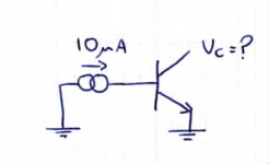
There's a famous question on linkedin that sparked everyone's mind as although looking like the simplest one, really complex :
A little analogue brain teaser for you ...
Attachments
And when somebody shows you the direction in a deep forest, you don't ask why: Music and Audio ElectronicsOPA2228(or 2227) is ze best
Pioneer CT-95 / T-1100S up close and personal - Tapeheads Tape, Audio and Music Forums
OPA1611 has 1.7 pA/(Hz) worth of current noise (essentially as much as LM4562), that's a tad on the high side. Tape EQ doesn't have the very heavy downwards slope of RIAA EQ, it would penalize high current noise levels even more.It would seem that MM phono and tape head repro amps have a lot in common----both are very low level (a coupla mV), are inductive sources, and are amplifying signal sources with less-than-ideal signal-to-noise ratios. I am still looking for a single opamp for tape heads---considering NE5534, OPA 1641, and OPA1611. What are you finding?
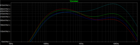
Adapting my phono preamp noise sim w/ A-weighting to the NAB preamp circuit (with head = 650R + 560 mH, input Z = 10p || 40k) gave this:
That's 20 dB on the vertical. Not minor differences!
Red: OPA6141
Green: LM833
Blue: NE5534A
Teal: LM4562
The classic NE5534A isn't such a bad deal right out of the box, and being partially decompensated, also is somewhat faster than e.g. the NJM2068 (a part otherwise very similar in noise). It can also be hacked in several ways, e.g. deactivating and replacing its input stage altogether, only the AD744 is even more flexible.
OPA1656 may also be promising, despite its relatively high 1/f corner. I'll have to try and work that in (currently 1/f noise is not being taken into account). It's got high GBW right out of the box. Tape preamp circuits tend to use highish gain by nature, so instability should rarely be an issue.
BTW, while I haven't gotten around to writing the article on everyman's audio opamp selection yet that's been on my to-do list (somehow it just keeps growing while I'm on vacation), the section on jellybean opamps has been revamped recently. It was rather a mess and should be much easier to follow now. I am still unsure about which content to move to dedicated pages - I'm at over 400K of HTML even with the calculator bits already taken out, making this my second largest page. I do actually care about user experience a lot, it's just that I'm working within the confines of a bunch of handwritten static HTML pages.
Oh, and if you are willing to go down tape-realted rabbit holes, I'm sure you've seen this as well. It seems like tape EQ may well be worth a look at depending on what kind of speeds you are using. In any case I would very much be looking at playback noise levels with the tape stopped vs. running - if tape noise is smothering everything else, you might be barking up the wrong tree trying to optimize tape head preamps.
Ah yes, I think you mentioned. Better than my old portable Hameg for sure. Probably about the same age.Got a whole bag o' 100nFs. Learned about this practice from guru Rod Elliott. AND got a scope---my trusty ol' Tektronix 465 (ancient, I guess, but still a good piece of test gear)
Another part you may need to keep a stash of is very small caps, like 2-3 pF maybe. These can be handy to add in parallel to the feedback resistor, as otherwise input capacitance tends to appear in parallel to the ground leg resistor and cause ultrasonic peaking or even oscillation. It is generally seen with feedback resistor values of 10k and higher, though low-noise hot-rod parts may require this treatment as low as 1k.
Ideally the ratio of feedback capacitor and input capacitance should be the inverse of resistor ratio, but generally it works out to 5 pF max.
Ah well, that's a bit of a problem. I think it's different from the NE5534 pinout, too.Well, maybe a 55MHz IC is too fast for this old mixer, but......the OPA1688 is sorta slow & noisy, and I have a hard time trusting ANYthing from New Japan Radio due to their very sneaky datasheets. They try to hide stuff. Also, I'm hoping for something with a single op amp footprint, as it's a TL071 that's in there now.
Some creativity may be required there, like paralleling two OPA1688s and combining their outputs much like the O2 headphone amp does. (I don't think anyone makes an adapter board like this, now do they?) And then you get 5.6 nV/√(Hz), hardly an input noise level worth complaining about.
I know what you mean by "sneaky" datasheets, but I would blame the datasheet trends of the '80s for this as much as anything, which is how old these parts generally are. At that time manufacturers were getting increasingly tight-lipped, I think both because of fear of their devices being cloned and to conserve space in their ever thicker databooks. Only in the digital age have comprehensive datasheets become more common again.
30 dB is still rather a lot. With all your mods, you should be able to run a fair bit higher internal levels, and not require that much attenuation.Yes, it is -30 db. I missed this before, but it's actually labeled as such on the panel next to the line/mic switch. I am thinking to just let it be at this point; before I was concerned about overloading, but now that doesn't seem to be a problem; the CFP mod should offer a dramatic improvement in the front end.
Attachments
Last edited:
That's what I've been thinking also. I found some NOS Philips NE5534N ICs that I am going to use in my tape preamp applications. Seems to be the best bang for the buck, and probably better than the tape itself.The classic NE5534A isn't such a bad deal right out of the box......
THAT is a VERY interesting article! Thanks for pointing it out. I do disagree, however, with your assessment that the NJM2043 has lower noise than the NE5534A---once again, the NJR spec sheet 'cheats' a little by quoting 'A' weighted noise specs in their tables; but if you look further down on the graphs, they do show the 'flat' noise, and it definitely appears to be worse than the 5534....... the section on jellybean opamps has been revamped recently.
My thought on that is that if Studer engineers deemed the NE5532 as the best for their tape audio electronics in the later years of production, I'm inclined to agree that an excellent I.C. well may make a viable difference. Their tape machines are certainly among the best ever made..... if you are willing to go down tape-related rabbit holes,.......... I would very much be looking at playback noise levels with the tape stopped vs. running - if tape noise is smothering everything else, you might be barking up the wrong tree trying to optimize tape head preamps.
Hmmmm.... a good point, but I can't seem to find input capacitance specification on any IC datasheets. How do I determine that?Another part you may need to keep a stash of is very small caps, like 2-3 pF maybe. These can be handy to add in parallel to the feedback resistor, as otherwise input capacitance tends to appear in parallel to the ground leg resistor and cause ultrasonic peaking or even oscillation. It is generally seen with feedback resistor values of 10k and higher, though low-noise hot-rod parts may require this treatment as low as 1k. Ideally the ratio of feedback capacitor and input capacitance should be the inverse of resistor ratio, but generally it works out to 5 pF max.
Nope, they're the same---standard single op amp pinnage.I think it's [TL071 pinout] different from the NE5534 pinout, too.
I'll look into that, and maybe lower the attenuation.30 dB is still rather a lot. With all your mods, you should be able to run a fair bit higher internal levels, and not require that much attenuation.
A couple of questions on your very good article:.... the section on jellybean opamps has been revamped recently. It was rather a mess and should be much easier to follow now.
- No mention of some very good, fairly low-cost opamps, such as the LM4562 and OPA1642----?????
- I noted your warnings about the T.I. versions of the NE5532; those have been verified by others as well. Have you evaluated the ON Semi version of the NE5532? Unfortunately, it appears to only be available in SOIC-8, but that's not a total game-breaker. Is there a viable NJM (or other) version of the NE5532 that would be better than the T.I. part?
"Upon further review......."I do disagree, however, with your assessment that the NJM2043 has lower noise than the NE5534A---once again, the NJR spec sheet 'cheats' a little by quoting 'A' weighted noise specs in their tables; but if you look further down on the graphs, they do show the 'flat' noise, and it definitely appears to be worse than the 5534.
I re-read the "Op Amp Measurement" by NwAvGuy, and I see that he says:
"NE5532 NOISE: The professional audio favorite, the NE5532, is about 3 dB worse at 7X gain than the less expensive and less current hungry NJM2068 above but still very quiet. I have heard some versions of the 5532 are a few dB better than others. This was a TI NE5532AP."
So it appears that, indeed, the NJM2068 does measure lower noise than the NE5532 or the LM4562. But the NE5534A should measure lower than the 4562 or the 5532. However, at 100 db down, noise really doesn't matter except maybe in mic preamp applications. Vinyl and tape are both way noisier than that, and at line level, noise of any of these opamps is inaudible.
Last edited:
Finally..."Upon further review......."
I re-read the "Op Amp Measurement" by NwAvGuy,
OP here, returning months later! Maybe my notifications went into my spam folder, I had no idea folks were here and interested. Apologies.
14 pages of comments!! Wow. A lot to take in here. Looks like quite a few people have been helping rehash this old $1 micpre in quite some detail. I do have plans to try the INA217 in my comparison too, eventually.
Mostly my efforts for the past months have been based around sound treatment for the studio, and building the furniture for the desk to live in, which came out pretty good. Best photo I could find:

Left to right, it's 16x Soundcraft 1600 input strips (model 8011), the master section, 8x Soundcraft 1600 subgroups, and then 10x Soundcraft 400b input strips over on the far right. Obscured by a drum machine sorry.
I'm currently in COVID-19 lockdown here in New Zealand and can't get near the desk for at least a few more weeks, but I did have a few spare 400b channels at home, so I finally got round to making up a wiring loom to connect them up to the 1600.

If anyone happens to have a 1600 or 800b handy, I'd love a photo of the copper side of the input channel or subgroup PCB, particularly around the IDC connector! Pin 1 isn't marked on the 1600 service manual schems, so I'm not sure exactly what orientation to put the IDC connector on the adapter board I'm building...
14 pages of comments!! Wow. A lot to take in here. Looks like quite a few people have been helping rehash this old $1 micpre in quite some detail. I do have plans to try the INA217 in my comparison too, eventually.
Mostly my efforts for the past months have been based around sound treatment for the studio, and building the furniture for the desk to live in, which came out pretty good. Best photo I could find:
Left to right, it's 16x Soundcraft 1600 input strips (model 8011), the master section, 8x Soundcraft 1600 subgroups, and then 10x Soundcraft 400b input strips over on the far right. Obscured by a drum machine sorry.
I'm currently in COVID-19 lockdown here in New Zealand and can't get near the desk for at least a few more weeks, but I did have a few spare 400b channels at home, so I finally got round to making up a wiring loom to connect them up to the 1600.
If anyone happens to have a 1600 or 800b handy, I'd love a photo of the copper side of the input channel or subgroup PCB, particularly around the IDC connector! Pin 1 isn't marked on the 1600 service manual schems, so I'm not sure exactly what orientation to put the IDC connector on the adapter board I'm building...
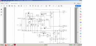
As promised earlier, here's the cap values I have been using during the recap so far.

Note that I haven't done the 'transamp mod' to any channels yet, although it's shown on this schem.
* Opamp following the micpre changed from TL072 to LM4562
* 22uF DC coupling caps are now 220uF
* The 2.2uF fader cap is 47uF
* Board PS decoupling caps have been increased from 22uF to 100uF
* Mic input caps have been raised from 47uF to 470uF
* Line input gain decouping cap increased from 100uF to 470uF
* All the film caps replaced with WIMA FKP2 or other polyprop film where the WIMAs aren't available
Note that I found some value changes Jim Williams recommended to expand the range of the HPF and EQ sections that are reflected on this schem.
Hope this helps somebody with their future recap job.
- Home
- Source & Line
- Analog Line Level
- Interesting Soundcraft 1600 mod results