Did you use a single Zobel network after the 0.33 Ohm resistors or two Zobel networks directly on the two amplifier outputs?
......2 zobel directly. but in the bpa instructions there are no zobels in the schematics, i would not worry about that.
aside this i measured the 1% res (and the elcap) with my DMM and selected these for less tolerance.
FF, compensate the lm4562 with 10p and 1k to start with , says TINA. You end with distortion 0.00012%.
Many thanks for seeking guidance from TINA. I know Tina as a girls name but I assume it is a simulation program as well.
I put up the circuit yesterday and did initial tests. 10pF is just stable, as you calculated, until I used a square-wave signal and that triggered oscillation. I will increase the value to have a stability margin. I calculated the loop-gain and arrived at an assumed THD level close to your result. I am very happy with this value.
I still need to dampen the response to square-wave signals and one possibility is to reduce the slew-rate of the OP-AMP with capacitive loading straight from the OP-AMP output to ground. Apart from that, the circuit works.
Refer to post #465 by Preamp for his circuit that this modifies.
Changes have only been tested in LTSpice simulation.
Changed a few resistor & capacitor values.
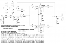
Changed feedback ground resistor/capacitor to a single ground resistor/capacitor. Attempting to get electrolytic capacitors of exactly equal value would be near impossible. If they vary in value then the gain will change depending on the frequency. Imbalancing this circuit can mean dead opamps. All resistors R1, R6, R5, R12, R10, R3, R13, R14 should be 0.1% tolerance as both LM1875 circuits have to be matched for gain and equal output current and power dissipation. See application note AN-1192 Overture Series application note for more info, which are more like caveats.
Changed zobel network to single at output.
Output appears clean on a square wave as long as voltage is below clipping level. All other results are in the attached picture. All AC voltages and AC currents shown in notes in picture are peak not rms.
Easy way to calculate power from waveforms in LTSpice:
Power_rms = Vout_pk x Iout_pk / 2
Can someone check for errors. Also changes welcome.
Changes have only been tested in LTSpice simulation.
Changed a few resistor & capacitor values.
Changed feedback ground resistor/capacitor to a single ground resistor/capacitor. Attempting to get electrolytic capacitors of exactly equal value would be near impossible. If they vary in value then the gain will change depending on the frequency. Imbalancing this circuit can mean dead opamps. All resistors R1, R6, R5, R12, R10, R3, R13, R14 should be 0.1% tolerance as both LM1875 circuits have to be matched for gain and equal output current and power dissipation. See application note AN-1192 Overture Series application note for more info, which are more like caveats.
Changed zobel network to single at output.
Output appears clean on a square wave as long as voltage is below clipping level. All other results are in the attached picture. All AC voltages and AC currents shown in notes in picture are peak not rms.
Easy way to calculate power from waveforms in LTSpice:
Power_rms = Vout_pk x Iout_pk / 2
Can someone check for errors. Also changes welcome.
Attachments
Last edited:
Listen again the Turtles song.
I will when I have inserted the feedback components in a more tidy way. Last evening was only the first somewhat primitive tests because I was curious to see if it could run with such relatively high loop gain. I also need to dampen the SQ-wave overshoot.
Refer to post #465 by Preamp for his circuit that this modifies.
Changes have only been tested in LTSpice simulation.
Changed a few resistor & capacitor values.
Changed feedback ground resistor/capacitor to a single ground resistor/capacitor. Attempting to get electrolytic capacitors of exactly equal value would be near impossible. If they vary in value then the gain will change depending on the frequency. Imbalancing this circuit can mean dead opamps. All resistors R1, R6, R5, R12, R10, R3, R13, R14 should be 0.1% tolerance as both LM1875 circuits have to be matched for gain and equal output current and power dissipation. See application note AN-1192 Overture Series application note for more info, which are more like caveats.
Changed zobel network to single at output.
Output appears clean on a square wave as long as voltage is below clipping level. All other results are in the attached picture. All AC voltages and AC currents shown in notes in picture are peak not rms.
Easy way to calculate power from waveforms in LTSpice:
Power_rms = Vout_pk x Iout_pk / 2
Can someone check for errors. Also changes welcome.
I find the single C5 a very interesting idea that can eliminate different dynamic behavior from the two LM1875. If a single Zobel network after the load-balancing resistors is as good as two separate directly on each output, needs to be evaluated in test as I guess the simulation model may not be very precise on such behavior.
In my eyes, R17 leaves a frequency independent pretty low loop-gain that does not leave much distortion-correction in that loop.
Last edited:
Originally Posted by RufusGartz (Annex post 484) o.a
"Vcc=22v, Vin = 1.37v pk, Vout=19.156v pk Iout=2.39A, Power_rms output = 22.89 watts approx"
Is that the simulated outcome of 2x LM1875 (paralleled) at +/-22V powersupply?
I had expected a (much) higher output, with my present non-composite setup (single LM1875 at about 22V) it allready outputs about 25W.
Is that the simulated outcome of 2x LM1875 (paralleled) at +/-22V powersupply?
I had expected a (much) higher output, with my present non-composite setup (single LM1875 at about 22V) it allready outputs about 25W.
i guess its into 4R
chris
Is that the simulated outcome of 2x LM1875 (paralleled) at +/-22V powersupply?
I had expected a (much) higher output, with my present non-composite setup (single LM1875 at about 22V) it allready outputs about 25W.
Hi Fred,
With two LM1875 in parallel, the total of the two can handle double the current. But, if you do not use that current to drive a load with half the impedance and still use 8 Ohm, the output power remains the same. Rufus calculates 23W, you measure 25W in 8 Ohm - that is close. It is only when you use 4 Ohm or use a BTL coupling with an 8 Ohm load that you have a real increase in output power. Rufus calculates 40W in 4 Ohm.
Last edited:
Thanks FauxFrench for the explanation, it is all clear (and nicely confirmed by the 4 ohm
outputs also given by RufusGartz in the same Annex)
outputs also given by RufusGartz in the same Annex)
I finally implemented 100pF (foil) and 6K2 in series as feed-back for the OP-AMP in my composite amplifier. Good stability but an important over-shoot at the output of the OP-AMP with a fast square-wave at the input due to the OP-AMP being faster than the power stage. For frequencies in the audio-band it is not a problem. I will try to clamp the output amplitude of the OP-AMP.
I measured an output off-set of 10mV (0.5mV at the OP-AMP input) and noticed that the "pop" at start-up and shut-down now appeared. It is most likely due to OP-AMP reaching its operational equilibrium slower that the power stage. Still no hiss or hum.
Tested the amplifier on the speakers with different kind of music inclusive Turtles "Happy together". I found no artefacts and the bass is powerful. With Turtles, the choir (and some trumpets I believe) was still transparent.
I calculated the loop-gain at 1KHz to around 120. That should bring the overall THD to the level 0.000X% as measured by palstanturhin. Exactly how much, my ears cannot tell and my present sound-card does not allow tests below 0.00X%.
I will experiment with OP-AMP output clamping and my better regulated power supply before constructing the other phase-inverted half.
Last edited:
 ...very good FF
I got my regulated symmetrical power supply on it tonight. Very low dynamic output impedance. A quick test with +/-24V supply and 4 Ohm indicates much less "woolly" saturation tops than with my unregulated supply. I will try to take photos tomorrow.
With my low-impedance regulated power supply adjusted to +/-22Vdc and with 1KHz at the input, I got the following results:
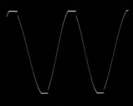
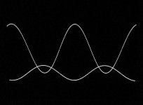
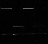
Pict.1: Clipping at 36Vpp in 2.7 Ohm. Vertical part due to recovery of OP-AMP output.
Pict.2: Square-wave at 15Vpp in 2.7 Ohm. Spikes at start difficult to see.
With my regulated power supply, the clipped flat tops are much less "woolly" than with the unregulated power supply.
I will try to remove the SQW start spikes by clamping the OP-AMP output.
Attachments
Last edited:
With the regulated supply the voltage is kept constant even with the amp driven into clipping. The unregulated supply interacts with the clipping amp, as it´s voltage breaks in at load. That is the difference and what you expect from a "stabilized" supply.
Nice to see it so clearly.
Don´t come to the conclusion regulated will sound better, you will never listen to an amp clipping that much, but rather buy or build a stronger amp if you must hear that loud.
Nice to see it so clearly.
Don´t come to the conclusion regulated will sound better, you will never listen to an amp clipping that much, but rather buy or build a stronger amp if you must hear that loud.
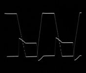
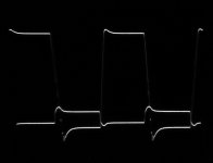
An inherent problem with composite amplifiers seem to be the difference in reaction-speed of the OP-AMP and the power AMP(s). Normally the OP-AMP reacts faster than the power AMP(s) and remains in the linear working area when the power AMP(s) saturate. That leaves unpleasant dynamic spikes when tested with a square-wave at the input. The OP-AMP output tends to make large voltage excursions if not clamped to remain in the linear area and to avoid unnecessary large excursions. I implemented a very simple amplitude clamp – two 4V7 zener diodes back-to-back, from the output pin and back to the inverting input. That can only be expected to leave increased distortion at high amplitudes but it improves dynamic behavior.
A better amplitude clamp can be implemented but with my compact Vero-board design, only simple solutions fit in.
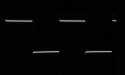
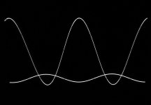
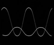
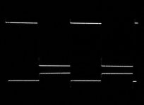
I tested with my regulated power supply at +/-22V and with 20KHz input. 2.7 Ohm load. The dynamic behavior is improved wile the increase in distortion cab be seen at amplitudes near saturation of the power AMPs.
The upper curve is the power output, the lower curve the output of the OP-AMP.
Picture 1: 10Vpp
Picture 1: 10Vpp
Picture 1: 20Vpp
Picture 1: 20Vpp
Picture 1: 30Vpp
Picture 1: 30Vpp
Picture 1: Clipping at 35Vpp
Picture 1: Clipping at 35Vpp
Remember that these test results are at 20KHz, thus at the very top of the audio band. I will try to repeat the measurements at 1KHz.
A better amplitude clamp can be implemented but with my compact Vero-board design, only simple solutions fit in.
I tested with my regulated power supply at +/-22V and with 20KHz input. 2.7 Ohm load. The dynamic behavior is improved wile the increase in distortion cab be seen at amplitudes near saturation of the power AMPs.
The upper curve is the power output, the lower curve the output of the OP-AMP.
Picture 1: 10Vpp
Picture 1: 10Vpp
Picture 1: 20Vpp
Picture 1: 20Vpp
Picture 1: 30Vpp
Picture 1: 30Vpp
Picture 1: Clipping at 35Vpp
Picture 1: Clipping at 35Vpp
Remember that these test results are at 20KHz, thus at the very top of the audio band. I will try to repeat the measurements at 1KHz.
Attachments
-
 Limit1875_20KHz_Clip35Vpp_2.7Ohm_SQ.jpg218.2 KB · Views: 73
 -
 Limit1875_20KHz_Clip35Vpp_2.7Ohm.jpg234.2 KB · Views: 67
 -
 Limit1875_20KHz_30Vpp_2.7Ohm_SQ.jpg246.3 KB · Views: 71
 -
 Limit1875_20KHz_30Vpp_2.7Ohm.jpg288.9 KB · Views: 79
 -
 Limit1875_20KHz_20Vpp_2.7Ohm_SQ.jpg379 KB · Views: 79
 -
 Limit1875_20KHz_20Vpp_2.7Ohm.jpg165.3 KB · Views: 247
 -
 Limit1875_20KHz_10Vpp_2.7Ohm_SQ.jpg299 KB · Views: 240
 -
 Limit1875_20KHz_10Vpp_2.7Ohm.jpg237.7 KB · Views: 257
With the regulated supply the voltage is kept constant even with the amp driven into clipping. The unregulated supply interacts with the clipping amp, as it´s voltage breaks in at load. That is the difference and what you expect from a "stabilized" supply.
Nice to see it so clearly.
Don´t come to the conclusion regulated will sound better, you will never listen to an amp clipping that much, but rather buy or build a stronger amp if you must hear that loud.
I fully agree with you that better looking curves do not necessarily mean better sound. But to palstanturhin: this is the way to battle the fine oscillation at the saturated tops. To others - this demonstrates the difference and advantage of using a regulated power supply. Better looking curves but more importantly a voltage that remains constant disregarding loading. At low loading the amplifier is not stressed from a high supply voltage and at high loading, the voltage remains constant such that you get the output power you expect. Remember that my +/-24V unregulated power supply dropped to +/-18V with hard loading!
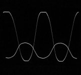
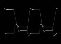
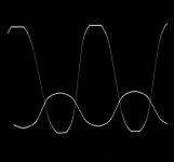
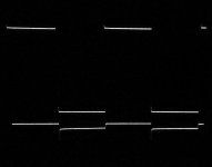
And now the results with amplitude-clamp and 1 KHz. Else, same conditions as above.
Picture 1: 10Vpp
Picture 2: 10Vpp
Picture 3: 20Vpp
Picture 4: 20Vpp
Picture 5: 30Vpp
Picture 6: 30Vpp
Picture 7: Clipping at 35Vpp
Picture 8: Clipping at 35Vpp
The very steep change of levels (slope) for square-wave is unrealistic with music.
Picture 1: 10Vpp
Picture 2: 10Vpp
Picture 3: 20Vpp
Picture 4: 20Vpp
Picture 5: 30Vpp
Picture 6: 30Vpp
Picture 7: Clipping at 35Vpp
Picture 8: Clipping at 35Vpp
The very steep change of levels (slope) for square-wave is unrealistic with music.
Attachments
-
 Clip1875_1KHz_Clip35Vpp_2.7Ohm.jpg291.4 KB · Views: 67
 -
 Clip1875_1KHz_30Vpp_2.7Ohm_SQ.jpg150.1 KB · Views: 74
 -
 Clip1875_1KHz_30Vpp_2.7Ohm.jpg254.3 KB · Views: 74
 -
 Clip1875_1KHz_20Vpp_2.7Ohm_SQ.jpg225.2 KB · Views: 76
 -
 Clip1875_1KHz_20Vpp_2.7Ohm.jpg213.1 KB · Views: 75
 -
 Clip1875_1KHz_10Vpp_2.7Ohm_SQ.jpg508.1 KB · Views: 73
 -
 Clip1875_1KHz_10Vpp_2.7Ohm.jpg291.4 KB · Views: 74
 -
 Clip1875_1KHz_Clip35Vpp_2.7Ohm_SQ.jpg260.1 KB · Views: 75
Last edited:
I listened to the amplifier with all the test music from before and I could not hear any difference from last test.
Then, I made my first quick test with the UTC-TDA2050V. I used my test-board with -3.5 times gain. I noticed no difference in performance from my good "fake" LM1875. The stability seems identical. Even "woolly" saturated tops. Wonder if my fake LM1875 are actually TDA2050 chips?
Then to the critical short-circuit survival test 😱 ! +/-18V supply and short-circuit of the output at start-up. IT WORKED!. When the short-circuit was removed it played on. Goooood chip .
.
Then, I made my first quick test with the UTC-TDA2050V. I used my test-board with -3.5 times gain. I noticed no difference in performance from my good "fake" LM1875. The stability seems identical. Even "woolly" saturated tops. Wonder if my fake LM1875 are actually TDA2050 chips?
Then to the critical short-circuit survival test 😱 ! +/-18V supply and short-circuit of the output at start-up. IT WORKED!. When the short-circuit was removed it played on. Goooood chip
.Originally posted by FauxFrench:
That exactly comfirms my findings!
Did you perhaps also check the dissipation/ temperature of the chip?
Given the very similar results you experienced (in comparison to the "LM1875") and the current limit of 5A peak of the UTC-TDA2050 isn't this chip the preferred choice?
Two paralleled UTC's will probably give comparable results to three LM1875's which might simplify the project somewhat.
Also the working built-in protections are an advantage at (almost) comparable cost.
Then to the critical short-circuit survival test ! +/-18V supply and short-circuit of the output at start-up. IT WORKED!. When the short-circuit was removed it played on. Goooood chip
That exactly comfirms my findings!
Did you perhaps also check the dissipation/ temperature of the chip?
Given the very similar results you experienced (in comparison to the "LM1875") and the current limit of 5A peak of the UTC-TDA2050 isn't this chip the preferred choice?
Two paralleled UTC's will probably give comparable results to three LM1875's which might simplify the project somewhat.
Also the working built-in protections are an advantage at (almost) comparable cost.
- Home
- Amplifiers
- Chip Amps
- LM1875 in parallel configuration and used in a composite amplifier.