remember that it is part of an amplification chain. 0.03% in total is quite different from 0.03% getting amplified and more distorted. If you see it differently, that's ok. It is good that we get honest numbers so that we understand the parts we are working with.My goodness poor audiophiles.....0.03%, and likely 0.3% is already completely inaudible 😀, but off course the lower numbers will make you "feel" better 🙄
The SMPS1200 by default comes configured to deliver ±12 V for the opamp. You can use that if you don't want to mess with regulators on the buffer board.
Tom
Hi Tom,
Are you sure ?
According to the datasheet, auxiliary voltages outputs are around +/- 20-22V and not +/-12V. And at least it is what I can measure on my samples...
Jean Claude
remember that it is part of an amplification chain. 0.03% in total is quite different from 0.03% getting amplified and more distorted. If you see it differently, that's ok. It is good that we get honest numbers so that we understand the parts we are working with.
0.03% amplified is still 0.03%.
You have three voltages, HV, Vaux and a Vdr, a bootstrap driver voltage. The Vdr seems to be 15V but relative to the HV-.
Unfortunately, amplifiers will also amplify and distort the distortion components. No amplifier (tube, solid state etc.) is completely linear, so each step adds a little bit which is why often correction (feedforward/feedback) is used. I leave it at that.0.03% amplified is still 0.03%.
I agree that audiophile levels start at 0,0* beyond that its more or less just a number 🙂My goodness poor audiophiles.....0.03%, and likely 0.3% is already completely inaudible 😀, but off course the lower numbers will make you "feel" better 🙄
Unfortunately, amplifiers will also amplify and distort the distortion components. No amplifier (tube, solid state etc.) is completely linear, so each step adds a little bit which is why often correction (feedforward/feedback) is used. I leave it at that.
I agree that each stage adds an additional contribution, but the fact that an amplifier has gain doesn't affect the distortion of the previous stage.
What you wrote was "0.03% in total is quite different from 0.03% getting amplified and more distorted". No, it isn't. Not for the "amplified" part.
Let's assume you have a 1 V signal with 0.03% THD, so 0.03 V of harmonics and noise. Amplify that by a factor of 10. Now you have a 10 V signal with 0.3 V of harmonics and noise. Still 0.03%.
This buffer board is very interesting.
But as it's dual mono you need a Y cable to connect both buffer and SMPS1200, no way to chain the two buffer ?
About the power supply choice... I just look over the internet and don't see much info of a purifi power supply. It was suppose to have better idle consumption compare to the smps1200, which i value a lot.
I read cresnest will offer a power supply for the purifi, but again not much news.
In my point of view, when i will build a purifi amp soon, i won't use a linear power supply and use the silent switcher if i can. No point of building a class d, especially as the purifi was build with power consumption in mind, to add a linear power supply like the diyinhk with lt3045. I agree it's not like powering the whole amp with linear, and for the opamp a linear is not so much of a waste, but still it's not the same efficiency...
I agree that the silent switcher is suppose to have more noise, arround 4uV, for 0.5uV for the idyinhk which is 8x more... but honestly, is their really a earable difference between the two ? I use the silent switcher with my dam1941, cannot complain of anything.
Hi Tom,
Are you sure ?
According to the datasheet, auxiliary voltages outputs are around +/- 20-22V and not +/-12V. And at least it is what I can measure on my samples...
Jean Claude
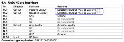
Your values are for UNregulated output. One can get +Vaux from the Hypex SMPS1200A400 either regulated (default), or UNregulated, set by a jumper configuration. That is what Tom was describing. With the EVAL1 set, since there IS a local regulator, you want to use the UNregulated output from the SMPS1200. For Tom's board, as-is, you use either your own external supply, OR the regulated output of the SMPS1200. Alternatively, he says he will offer a means of adding a local regulator. In that case, one could (I presume, pending specs) use the UNregulated output of the SMPS1200. From the datasheet:
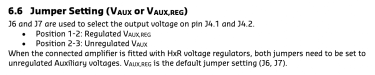
J6 and J7 are used to select the output voltage on pin J4.1 and J4.2.
• Position 1-2: Regulated VAUX,REG
• Position 2-3: Unregulated VAUX
When the connected amplifier is fitted with HxR voltage regulators, both jumpers need to be set to
unregulated Auxiliary voltages. VAUX,REG is the default jumper setting (J6, J7).
Last edited:
Tom, if it can be provided, it would be great to have a hole to wire the loop feedbacks from the output connector, rather than on board, like can be done with the EVAL1. A universal option could be a 1 ohm link on-board (to ensure the amp would never be open loop, accidentally), with a jumper to bypass it on-board. That way, feedback would be on-board by default, but could be from off-board by removing the jumper.
Tom, if it can be provided, it would be great to have a hole to wire the loop feedbacks from the output connector, rather than on board, like can be done with the EVAL1. A universal option could be a 1 ohm link on-board (to ensure the amp would never be open loop, accidentally), with a jumper to bypass it on-board. That way, feedback would be on-board by default, but could be from off-board by removing the jumper.
I have seen this option on the Purifi boards and I am not 100% sure what the purpose of having the feedback off-board would be.
Y. From the datasheet:
J6 and J7 are used to select the output voltage on pin J4.1 and J4.2.
• Position 1-2: Regulated VAUX,REG
• Position 2-3: Unregulated VAUX
When the connected amplifier is fitted with HxR voltage regulators, both jumpers need to be set to
unregulated Auxiliary voltages. VAUX,REG is the default jumper setting (J6, J7).
You are right, in fact I built several years ago a pair of SMPS1200 with NC1200 power amplifiers and I wrote my false comment from memory.
Sorry
Jean Claude
I have seen this option on the Purifi boards and I am not 100% sure what the purpose of having the feedback off-board would be.
To includes any contact loses or 'distortion' in the feedback loop. It is what Purifi did on their demonstration units, like the one tested at audiosciencereview.com. It maximizes damping factor (lowers net output impedance). It compensates for ALL the contacts and PCB traces from the amp module to the output connector. It is a minor refinement, but when modding for 'perfection', it would be nice to be able to use the available capabilities, fully.
Are you sure ?
Yes.
According to the datasheet, auxiliary voltages outputs are around +/- 20-22V and not +/-12V. And at least it is what I can measure on my samples...
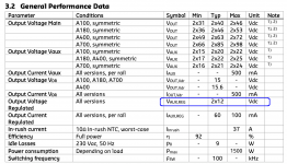
Really? Attached figures are screen shots from the SMPS1200 data sheet. I'm curious how you arrived at the conclusion that a regulated supply is not available. In particular as the SMPS1200 ships with the regulated supply enabled. This default setting is also specified in the data sheet (and the one I received was set from the factory to provide the regulated supply).
To me, the data sheet is pretty clear. You can select between the unregulated (±15 V to ±24 V, depending on condition) and the regulated (±12 V) supply using a pair of jumpers (J6, J7). That has also been my experience with the SMPS1200.
Tom
Attachments
I have seen this option on the Purifi boards and I am not 100% sure what the purpose of having the feedback off-board would be.
The purpose is to compensate for the loss across the speaker wire. Ideally, you'd run the remote sensing leads all the way to the speaker terminals (not just to the output terminals of the amp). However, if that connection ever lets loose, your speaker cones will be in for a wild ride.
The area of the board around the speaker terminals is pretty bare, so I can certainly look into providing a 2-pin connector footprint and 1 Ω resistors.
Unfortunately, adding those two 1 Ω resistors will increase the assembly cost as the technician will need to load an additional part into the pick-n-place machine. He doesn't work for free, unfortunately.
Either way, this option would be for advanced builders only.
Tom
...
I can certainly look into providing a 2-pin connector footprint and 1 Ω resistors. Unfortunately, adding those two 1 Ω resistors will increase the assembly cost ...
Either way, this option would be for advanced builders only.
Tom
Thanks for the reply. I appreciate your careful work. Considering cost optimizing while facilitating potential advanced builds, do you already use 0R SMD on the board? Maybe you could make the on-board feedback path through another of those and provide a through hole on the feedback side (not the load side). Then one could remove/replace that 0R and wire up remote sensing. No added jumpers - just the cost of two 0R SMD. Just a thought...
I am considering adding separate feedback points on the back panel to take the feedback from the speaker wire side of the output connection (not all the way to the speaker).
Last edited:
Considering cost optimizing while facilitating potential advanced builds, do you already use 0R SMD on the board? Maybe you could make the on-board feedback path through another of those and provide a through hole on the feedback side (not the load side). Then one could remove/replace that 0R and wire up remote sensing.
I do use 0 Ω resistors. They could become 1 Ω resistors. That would allow for remote sensing with a fallback/failsafe should the feedback connection drop.
No added jumpers - just the cost of two 0R SMD.
...and their assembly cost. At that point we're pinching pennies, though. The biggest cost driver is the cost of loading the components into the PnP machine.
Tom
Warning, RE the Connex SMPS
I was doing some testing here with my Connex SMPS 800re and Purifi modules and found a problem. While testing with a "brown noise" file I use for break in/testing, the amp modules started intermittantly cutting out, with the indicator LEDs also going out. It appeared that the amp protection was kicking in. I measured the voltage rails while playing (nominally +/- 65 VDC) and saw the voltage jumping all over the place, including to well over 70 VDC.
I contacted Connex and asked them about it, and they suggested it must be due to power supply pumping, and suggested adding 4700 µF more capacitance to each voltage rail, and then to test again. I have not done that yet...
I would suggest that anyone using the Connex supplies with the Purifi modules, take the time to monitor the main power supply rails while driving the amps at a high level to be sure things are OK!
I am going to order a Hypex supply, and test the Connex SMPS 800re with additional capacitance as well. But even with the Hypex supply, I will continue to use the custom linear I built for the +/- 18 VDC supplies, as it is working perfectly.
And, thank you Purifi for having good protection features built into your modules!
Last edited:
TomC, as pertains to the discussion regarding the feedback connections, I am fine with you leaving the feedback loop only terminated at the speaker outputs on your boards. It is hard to imagine that running this via flying leads to the binding posts would really result in any improvement? Considering that the feedback loop has got to be a high speed signal path, it seems to me running it on flying leads and allowing DIYers to implement it any way they want might cause more problems than it solves?
In my thinking, just keeping the wiring to the binding posts as tidy and reasonably short as possible, with adequate gauge (12 AWG) should be fine.
In my thinking, just keeping the wiring to the binding posts as tidy and reasonably short as possible, with adequate gauge (12 AWG) should be fine.
I was doing some testing here with my Connex SMPS 800re and Purifi modules and found a problem. While testing with a "brown noise" file I use for break in/testing, the amp modules started intermittantly cutting out, with the indicator LEDs also going out. It appeared that the amp protection was kicking in. I measured the voltage rails while playing (nominally +/- 65 VDC) and saw the voltage jumping all over the place, including to well over 70 VDC.
I contacted Connex and asked them about it, and they suggested it must be due to power supply pumping, and suggested adding 4700 µF more capacitance to each voltage rail, and then to test again. I have not done that yet...
I would suggest that anyone using the Connex supplies with the Purifi modules, take the time to monitor the main power supply rails while driving the amps at a high level to be sure things are OK!
I am going to order a Hypex supply, and test the Connex SMPS 800re with additional capacitance as well. But even with the Hypex supply, I will continue to use the custom linear I built for the +/- 18 VDC supplies, as it is working perfectly.
And, thank you Purifi for having good protection features built into your modules!
This is somewhat to be expected when one uses a regulated 65V supply, since the regulation will defeat the tendency of the supply to sag under intense load and therefore inadvertently facilitate supply pumping. Apparently with their design Audiophonics incurred in this phenomenon with the Hypex supply as well and they declare they have done steps to mitigate that.
I know that the future Purifi power supply is going to be at 65V and regulated. This means that they must make sure that the increase in voltage is less than 8% in order not to trip protection. Indeed, this is one of the reasons I chose to pick the 54V supply (which was readily available from Audiophonics) and I did not order a custom one (and if I had had to, I would have probably ordered 60V not 65V).
- Home
- Amplifiers
- Class D
- Brainstorming Purifi 1et400a amps