Hi Greg,
It's strange that you are experiencing the bad output offset again - same issue as with your first board.
On the bad channel, what is the voltage drop across the 2K R resistor (R32 or R33, depending on the channel)? The output offset is 2mA so in order to null the offset, the circuit needs to supply 2mA through the pot and 2K resistor.
.002A x 2000R=4.0V should be the voltage drop across the 2K resistor if the circuit is working properly.
Also what is the value of your IV resistor? The current through your IV resistor = .43V/R
Ben
Last edited:
Greg,
Just to make sure you aren't getting shorts anywhere with the tinny balls in the solder paste; I assume you gave the board a good soak in an Acetone bath? Or Isopropyl Alcohol?
Just to make sure you aren't getting shorts anywhere with the tinny balls in the solder paste; I assume you gave the board a good soak in an Acetone bath? Or Isopropyl Alcohol?
Hi Greg,
As Ryan said, check for shorts. Take the TDA off and check for short at the analog output pin of the bad channel at the socket to Gnd. Also check to make sure that the output pin at the socket has a good connection to the pcb (not open circuit). With the TDA out, check for voltage across R32 (2K) and the IV resistor. If the circuit is not shorted there will be voltage drop across both resistors.
Also I remembered that Markos4553 had offset of about 40mV at his right channel output without digital signal inputted, but with the digital input in place, he was able to zero the offset (post #456 DIY TDA1541A PCB "D3").
Ben
Ryan,
This is an excellent question and you are absolutely correct, tons of solder balls even with low heat SMD paste. I flushed the board three times: PCB cleaner, then alcohol, then DEOXIT. Lots and lots of those balls got flushed. Also, i did find one Tantalum was bridged under the pad, C15.
Ben,
I think you are correct in that I've built two of these boards and the RIGHT channel always biases perfectly (with or without digital input), LEFT always at .4v shorted. So this has been with my cheapie R1. So, I ordered a known-good A chip. It arrives today, therefore, we will finally see!! I just don't think its a coincidence. I am not putting my S1 in this board until I see it bias up correctly with the A.
With the R1, on the left channel, the output is shorted to ground. Pull the chip, short goes away. I've checked every cap and every R in the circuit. I've also checked all the attenuator branches. No measured differences or shorts on the LEFT.
I will let you guys know this afternoon!
Cheers,
Greg
Ryan / Ben,
Looks like I do indeed have a short on that channel. The short doesn't appear until the circuit is energized, with or without chip installed. I've been checking every cap and R and have yet to find the shorted device.
Cheers,
Greg
Looks like I do indeed have a short on that channel. The short doesn't appear until the circuit is energized, with or without chip installed. I've been checking every cap and R and have yet to find the shorted device.
Cheers,
Greg
Ryan,
Should C58-59 be populated if I'm using my own I/V? I'm thinking not based on what your schematic says.
Thanks,
Greg
Should C58-59 be populated if I'm using my own I/V? I'm thinking not based on what your schematic says.
Thanks,
Greg
Ryan,
Should C58-59 be populated if I'm using my own I/V? I'm thinking not based on what your schematic says.
Thanks,
Greg
Yes you can leave them out.
Guess what everybody??
After months of problem solving I finally got the ref voltages correct (thank you Ben Mah and Ryan).
This thing is epic sounding. I have a very good streaming source that I built running an audiophile OS that you would not think makes a difference, but it makes a huge difference (Euphony Stylus).
So, with just my A chip in the thing is very musical!
All my PSUs are Salas designs.
The output is Abbas’: germanium I/V feeding a 5687 tube buffer.
Voltages are dead on and offsets are right around 0 at the output. Super quit
design.
I’m not running Simul yet, just wanted to get the D3 working first. The simul board was finished months ago and should be good.
I think I will put a D3 build guide together with Ryan’s blessing.

More good news. The S1 that I over volted to -20 on the -15vdc is making beautiful music.
Sounds noticeably better then the A.
Again, thanks everybody, especially Ben for all the encouragement and help.
I’ve never failed at any project and I wasn’t going to start with this one!
Sounds noticeably better then the A.
Again, thanks everybody, especially Ben for all the encouragement and help.
I’ve never failed at any project and I wasn’t going to start with this one!
The proof that the Simultaneous board works, which I soldered with just an SMD tip on my iron, including the U.Fls. which was completed before i got my air station.

The DAC in simultaneous mode is really amazing and again, with the effective bit depth equaling what modern, Delta-Sigma designs accomplish with "back end" noise shaping, and dithering, and filtering, ect.ect., I'm hearing every bit a of detail, but a smoother presentation, and no glare!
It would be one thing if you could get only a smoother presentation, but not the detail. With this DAC chip / 50hz DEM and the his layout and with Simultaneous data, you get all the detail!
Now I have an extra board which I may be able to get working plus an extra S1, so the question is should I go multiplex or build another with Cinemag OPS?
Cheers,
Greg
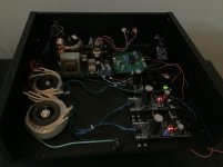
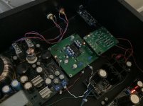
Here is a picture...View attachment 776973
Pistollero,
You really went all out with your JLsounds I2S board; 2 reflektor Ds, one powering the oscillator / reclock, another powering the USB bus.
Is that correct?
Cheers,
Greg
Hello Greg,Pistollero,
You really went all out with your JLsounds I2S board; 2 reflektor Ds, one powering the oscillator / reclock, another powering the USB bus.
Is that correct?
Cheers,
Greg
Thats correct but now i changed....
I have one reflector on tda 5v instead ultra bib and on jlsounds i dont use reflector on usb bus.. i m using a laptop on battery and i don t see diference in sound...
I m using simultaneous board fed by the same 5v tda reflector.
Ians fifo to simultaneous board..
.. i have not a stable setup... i m doing experiences with boards...
Hello Greg,
Thats correct but now i changed....
I have one reflector on tda 5v instead ultra bib and on jlsounds i dont use reflector on usb bus.. i m using a laptop on battery and i don t see diference in sound...
I m using simultaneous board fed by the same 5v tda reflector.
Ians fifo to simultaneous board..
.. i have not a stable setup... i m doing experiences with boards...
Experiments with various PSUs?
That's exactly my plan is to do get the galvanic isolation by powering the USB with a Reflektor D.
Cheers,
Greg
Psu's and the digital i2s boards also.Experiments with various PSUs?
That's exactly my plan is to do get the galvanic isolation by powering the USB with a Reflektor D.
Cheers,
Greg
Psu's and the digital i2s boards also.
Yeah, I've put a lot of effort into the data delivery side, but on the reclocker / oscillator side not, that's the last obstacle for this project.
However, it sound really good as is.
Cheers,
Greg
- Home
- Group Buys
- DIY TDA1541A PCB "D3"
