RaspberryPi4 can be configured as USB2 audio class 2 gadget. A few fixes to the gadget and controller code make it bitperfect duplex 768kHz/24bit/3ch standard USB audio class 2, the fixes are pushed upstream now. More fixes could make it much faster - currently the USB microframe contains only one 1024bytes isochronous packet (duplex 65Mbit/s), a change could incorporate multiple packets in one microframe. Load at max duplex speed + generating the gadget -> host 350kHz sine signal in sox while dumping the incoming data: low tens % of single CPU core. It's all about sufficiently large buffers to keep process switches at reasonable numbers, copying memory is fast.
Linux hosts communicate with the usb-audio gadget out of the box at any speed the device reports, windows stock usb drivers not tested yet for higher than 192kHz (not my devel target yet).
RPi4 has SPI controller with DMA support, IMO it would work with the ADC chips.
The HW has good online support, linux kernel excellent support (I communicated the existing gadget issues directly with the USB core developer in Synopsys). Being linux it has excellent debugging facilities.
IMO RPi4 could be used instead of the CPLDs/FPGAs, talking directly to the ADC via SPI on one side and analyzing PC via USB on the other side + doing some DSP if needed along the way. Linux usb-audio drivers would certainly accept large bitrates.
Analyzer applications - Arta, REW, VisualAnalyzer run excellently in linux. It's only about convincing their authors to accept samplerates > 192kHz (perhaps not available on windows left-behind USB drivers, but readily available in linux). Plus using the new low-latency java garbage collector for REW - to be tested.
All layers may need some work but IMO being open source + the available support it is all entirely realistic. Plus it would be available for everyone from that moment on for any project in the future. Of course most of it would be software work, as with everything today.
RaspberryPi4 can be configured as USB2 audio class 2 gadget. A few fixes to the gadget and controller code make it bitperfect duplex 768kHz/24bit/3ch standard USB audio class 2, the fixes are pushed upstream now. More fixes could make it much faster - currently the USB microframe contains only one 1024bytes isochronous packet (duplex 65Mbit/s), a change could incorporate multiple packets in one microframe. Load at max duplex speed + generating the gadget -> host 350kHz sine signal in sox while dumping the incoming data: low tens % of single CPU core. It's all about sufficiently large buffers to keep process switches at reasonable numbers, copying memory is fast.
Linux hosts communicate with the usb-audio gadget out of the box at any speed the device reports, windows stock usb drivers not tested yet for higher than 192kHz (not my devel target yet).
RPi4 has SPI controller with DMA support, IMO it would work with the ADC chips.
The HW has good online support, linux kernel excellent support (I communicated the existing gadget issues directly with the USB core developer in Synopsys). Being linux it has excellent debugging facilities.
IMO RPi4 could be used instead of the CPLDs/FPGAs, talking directly to the ADC via SPI on one side and analyzing PC via USB on the other side + doing some DSP if needed along the way. Linux usb-audio drivers would certainly accept large bitrates.
Analyzer applications - Arta, REW, VisualAnalyzer run excellently in linux. It's only about convincing their authors to accept samplerates > 192kHz (perhaps not available on windows left-behind USB drivers, but readily available in linux). Plus using the new low-latency java garbage collector for REW - to be tested.
All layers may need some work but IMO being open source + the available support it is all entirely realistic. Plus it would be available for everyone from that moment on for any project in the future. Of course most of it would be software work, as with everything today.
It can be done for sure... but it's big, ugly, consumes a lot of power compared to the other solutions and has a non-zero boot time. It would probably take less time to adapt existing STM32 USB UAC firmware for UAC 2.0, but maybe not.
Somewhat related, but I had to work with the Synopsis (DesignWare) USB controller a few years ago in a SoC similar to the Broadcom on the RPi and it was the biggest piece of garbage I have ever encountered. The list of errata was impressive and the Linux driver at the time barely worked. I am sure the driver improved, but we had to fix several bugs ourselves. Even so, it was riddled with USB babble errors and the occasional kernel oops depending on the device connected.
No problem, this is just my view. If there is a better more simple solution which is realistic to implement, good for everyone.
I prefer working on solutions where I have someone to turn at in case of a problem, with a clear track of history. Sure the linux dwc2 and dwc3 drivers (both controller and gadget) are constantly receiving patches but for me that is a sign of life and quite healthy future for that part. If I hit a problem, it can be (and is) ironed out quite fast and once for all.
Meanwhile I will continue working on gradual improvements of the RPi UAC2 gadget as I need it for my DSP projects.
No problem, this is just my view. If there is a better more simple solution which is realistic to implement, good for everyone.
I prefer working on solutions where I have someone to turn at in case of a problem, with a clear track of history. Sure the linux dwc2 and dwc3 drivers (both controller and gadget) are constantly receiving patches but for me that is a sign of life and quite healthy future for that part. If I hit a problem, it can be (and is) ironed out quite fast and once for all.
Meanwhile I will continue working on gradual improvements of the RPi UAC2 gadget as I need it for my DSP projects.
It's definitely an interesting option which comes with more transparency and possibly community support on the software side. Do you know what the latency through the system would be like when used as a gadget?
If low latency is a key parameter, this would not be the right way to go. In an OS solution like this a reliable large throughput is achievable only through larger buffers => larger latency.
For my measuring projects latency is not a critical factor. A long FFT with averaging takes much more 🙂
I have no real numbers, my guess is a few hundred ms min (with RT kernel) for reliable glitch-free operation from the HW input to the USB host.
One problem with increasing samplerate is that default buffer/fragment sizes are chosen for the general audio usage. The larger samplerate will then cut the resultant fragment time to reliably unservicable values (below 1ms) and the buffer/fragment sizes must be increased. If no such config on a given OS/driver exists (as is often the case in windows), ...
My latest project based on same concept, targeting evaluation audio OPA in 20k-200k band. SAR adc ad7984
PulSAR ADC PMODs [Analog Devices Wiki]
data processing on nucleo-H743 (stm32H743). Display 320x480, fft-32k, sampling up to 1.2Msps.
I came across ads127l in my initial research, but TI doesn't have affordable eval-module so I went with analog D. Have tested also single ended ad7983, ad7988-5 ( 7984 - diffe
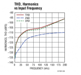
rential). Another suspicious nuance about ads127 is all I can see in DS specification for THD is only at 4kHz. What I observed with AD, that things is not goes well above 10kHz, THD drops and at 100k I hardly could get -90 thd-3.
Those are 18bit SARs, not really top performers. OTOH expecting better THD performance @100KHz is not realistic, I would think.
Agree, but professionally designed module makes my choice. Module, I mean ADC + driver + Ref. voltage.Those are 18bit SARs, not really top performers. OTOH expecting better THD performance @100KHz is not realistic, I would think.
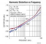
LTC2378-20 looks excellent in DS, until you start thinking how to drive this beauty. And here is surprise, Linear is using LTC6362 as SE-to-DIF & driver, page 8 shows "Harmonic Distortion vs Frequency" chart, and based on a picture thd-3 is about -97 at 20kHz. At the best - properly sized peak-to-peak sine wave. Real data is always worse.
An externally hosted image should be here but it was not working when we last tested it.
An externally hosted image should be here but it was not working when we last tested it.
Last edited:

Agree, but professionally designed module makes my choice. Module, I mean ADC + driver + Ref. voltage.
LTC2378-20 looks excellent in DS, until you start thinking how to drive this beauty. And here is surprise, Linear is using LTC6362 as SE-to-DIF & driver, page 8 shows "Harmonic Distortion vs Frequency" chart, and based on a picture thd-3 is about -97 at 20kHz. At the best - properly sized peak-to-peak sine wave. Real data is always worse.
An externally hosted image should be here but it was not working when we last tested it.
An externally hosted image should be here but it was not working when we last tested it.
LTC6362 are not the best option for driving the LTC2378, not sure why AD/LT decided for those opamps, I guess speed, not distortion, was the main scope of the eval board. I tried OPA1602 and OPA1632 and the THD distortions @20KHz are around -115dB FS differential. For the OPA1632, the analog board layout (symmetry) is extremely critical.
Right. LT shows one chart with outstanding performance (likely lab condition) and recommends to use OPA that can't get even close to those lab-data.LTC6362 are not the best option for driving the LTC2378, not sure why AD/LT decided for those opamps, I guess speed, not distortion, was the main scope of the eval board. I tried OPA1602 and OPA1632 and the THD distortions @20KHz are around -115dB FS differential. For the OPA1632, the analog board layout (symmetry) is extremely critical.
Do you mean you tried OPA1602/32 + LTC2378 ? Compatibility is an issue, what I noticed there are plenty nice OPA - but they miserably fail to drive SAR ADC. And those adc that performs good in lab environment, may demands OPA that didn't invented yet. Switching capacitors load has wide spectrum, and OPA with GBW less than 90 MHz likely to fail to drive 16-bits SAR at 10kHz input. Antialising filter doesn't help much, its attenuates RF components injected from ADC to OPA, and same time seriously loading output stage of the OPA.
Right. LT shows one chart with outstanding performance (likely lab condition) and recommends to use OPA that can't get even close to those lab-data.
Do you mean you tried OPA1602/32 + LTC2378 ? Compatibility is an issue, what I noticed there are plenty nice OPA - but they miserably fail to drive SAR ADC. And those adc that performs good in lab environment, may demands OPA that didn't invented yet. Switching capacitors load has wide spectrum, and OPA with GBW less than 90 MHz likely to fail to drive 16-bits SAR at 10kHz input. Antialising filter doesn't help much, its attenuates RF components injected from ADC to OPA, and same time seriously loading output stage of the OPA.
Yes. No compatibility issues that I can tell. The OPA1632 has the nice property of being able to set the output common mode voltage at half the reference without any hassle, the common mode voltage and single ended setup on the reference board is an abomination (one reason why I did not get it). OPA602 is on the ADC board, while the OPA1632 is on a differential amp PC board you can get from DigiKey for $15, cheaper than sending a design to a board house, and very good quality. If I remember correctly I used 499ohm 0.01% 0603 resistors.
ADA4945 is also a good option, and ADA4899 if you aren't wanting to use a fully differential op-amp for whatever reason.
While targeting much higher speed ADCs, there is an interesting series of articles by Derek Redmayne and Clarence Mayott of LT.
How to Drive the LTC2387 (Part 1): Signal Applications to 5MHz that Require Low Inter-Modulation Distortion | Analog Devices
Improving Linearity by Using Absorptive Filters | Analog Devices
Right. LT shows one chart with outstanding performance (likely lab condition) and recommends to use OPA that can't get even close to those lab-data.
Do you mean you tried OPA1602/32 + LTC2378 ? Compatibility is an issue, what I noticed there are plenty nice OPA - but they miserably fail to drive SAR ADC. And those adc that performs good in lab environment, may demands OPA that didn't invented yet. Switching capacitors load has wide spectrum, and OPA with GBW less than 90 MHz likely to fail to drive 16-bits SAR at 10kHz input. Antialising filter doesn't help much, its attenuates RF components injected from ADC to OPA, and same time seriously loading output stage of the OPA.
While targeting much higher speed ADCs, there is an interesting series of articles by Derek Redmayne and Clarence Mayott of LT.
How to Drive the LTC2387 (Part 1): Signal Applications to 5MHz that Require Low Inter-Modulation Distortion | Analog Devices
Improving Linearity by Using Absorptive Filters | Analog Devices
Last edited:
What I see, in the OPA1632 DS data specified for +-15V, everything - tables & charts. What voltage you apply to OPA?
Resistors 499 where, instead of 35 oHm? What about cap?
Could you post schematic?
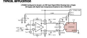
http://www.ti.com/lit/ug/snou023/snou023.pdf
R17=R18=R19=R20=499ohm 0.01%, all other resistors are either not installed or zero ohm. Decoupling capacitors are 10uF tantalum 1206 and 100nF ceramic, all other parts except the tantalum caps are 0603. T1 is also not installed.
OPA1632 running at +8V/-3V, at gain=1 output is well in the output swing range. I’ve also tried with great results ADA4945 but with the resistors 250ohm 0.01%. This one is even slightly more convenient to use, since it is rail-to-rail it can be fed from +6V/-1V without any problems. Both have the common mode voltage set to Vref/2=2.5V. If you use the compression mode of the LTC2378 you could even feed the ADA4945 from a single 5V supply (haven’t tried myself, though).
BTW, I punched a hole in my wallet and got the XMOS eval board XK-AUDIO-216-MC-AB XMOS | Development Boards, Kits, Programmers | DigiKey if anything, I believe it’s a great platform to experiment with, before exploring other ways. I’m a beginner, so I need to get my hands dirty before going further. I like the idea that the crappy ADC and DAC on board can be bypassed and connect my own stuff.
Thanks guys, just when I was about to clean my desk of this digital stuff you gave me something to think more about.
BTW, I have a raspberry pi 4 platform which I’m quite familiar with and I agree with Chris: placing a rpi between the ADC/DAC and the PC looks like an ugly solution, unless one would dare to give up the PC and build a standalone instrument, with the analyzer GUI running on the rpi as well. Not in my scope.
Having 8V and 35oHm resistor in series with 5V ADC could stress input OVP protection of the ADC up to 100mA - absolute maximum.http://www.ti.com/lit/ug/snou023/snou023.pdf
R17=R18=R19=R20=499ohm 0.01%, all other resistors are either not installed or zero ohm. Decoupling capacitors are 10uF tantalum 1206 and 100nF ceramic, all other parts except the tantalum caps are 0603. T1 is also not installed.
OPA1632 running at +8V/-3V, at gain=1 output is well in the output swing range. I’ve also tried with great results ADA4945 but with the resistors 250ohm 0.01%. This one is even slightly more convenient to use, since it is rail-to-rail it can be fed from +6V/-1V without any problems. Both have the common mode voltage set to Vref/2=2.5V. If you use the compression mode of the LTC2378 you could even feed the ADA4945 from a single 5V supply (haven’t tried myself, though).
PMOD is using 7.5V & -2.5V
PulSAR ADC PMODs [Analog Devices Wiki]
barely passing over-current limit and struggling to get as much voltage headroom for OPA as possible to minimize THD.
There is a new IC from microchip MCP6D11, low price, designed for 5V operation.
Having 8V and 35oHm resistor in series with 5V ADC could stress input OVP protection of the ADC up to 100mA - absolute maximum.
Don't think there's a significant risk, as far as I can tell from the schematics the LTC6362 opamps installed on the official eval board are also on +8V/-3V and they are high output current/rail to rail, worse that the OPA1632 from this perspective. The ADA4841 on those little eval boards can also swing to 50mV of the supply rails.
Last edited:
Yes, that true. Analog D. push to the limit voltage, 7.5 - 5 / 130 mA (abs. max) = 19.2 oHm. They installed 22. And negative -2.5V was a problem for me for a while. I was trying to stay on +5V power line from nucleo-H743 board, and do conversion for bipolar. Converter created a bunch of spikes on fft spectrum , I was not able to filter down to -120 dBc comming out from isolated DC-DC converters. At the end I used charge pump synchronized with ADC clock rate 1 MHz. There are no IC running at this speed, so have to design my own based on mosfet driver from microchip.Don't think there's a significant risk, as far as I can tell from the schematics the LTC6362 opamps installed on the official eval board are also on +8V/-3V and they are high output current/rail to rail, worse that the OPA1632 from this perspective. The ADA4841 on those little eval boards can also swing to 50mV of the supply rails.
Another issue I had with a module, is that for some reason input impedance 300 OHm - quite difficult to find OPA capable to drive such low input at 100kHz and have -120dBc and 5Vp-p.
Less than 12 hours since I received the XMOS multichannel eval board, I fully understand why Chris called this "XMOS garbage". Willingly or not, XMOS went a long way to sell something that is pretty much impossible to use with any degree of confidence in the project success. The list of crap is already too long to mention, and I'm only at the very beginning in exploring this practically undocumented junk baptized "open source hardware".
Well, I won't give up now, but it will take much more time than originally expected. Still not sure if starting from scratch with a DSP+ARM9 cores OMAP-L137 and using documented, tested and certified libraries is not a safer path to success...
Well, I won't give up now, but it will take much more time than originally expected. Still not sure if starting from scratch with a DSP+ARM9 cores OMAP-L137 and using documented, tested and certified libraries is not a safer path to success...

- Home
- Design & Build
- Equipment & Tools
- ADCs and DACs for audio instrumentation applications