Why, oh why, is there no community to speak off around this “open source” product? XCore Exchange - Index page is pretty much a dead place. Can I make a wild guess 😀?
I had no problems with their forum.
I had no problems with their forum.
It's there, and it does have info, but it's not exactly a hotbed of activity.
I did read the errata PDF for that Synopsys USB controller and it was pretty bad! No wonder it was tough making the driver work.
IME Synopsys devels are quite active and are interested in (e.g. paid by Synopsys for) making their implementations work properly.
The unfortunate thing about the Raspberry Pi is that it ends up with great Linux support, but Broadcom is really not interested in the ARM SoC market. So all that development work ends up only usable for the Raspberry Pi or RPi Compute Module and not for any broader set of hardware.
Yes and no. The linux drivers have layers, and lots of the work ends up helping other hardware implementations too. Especially true for the DWC core which gets used in many other SoCs (STM, TI OMAP etc.). Currently there is a big focus on the gadget functionality from multiple manufacturers (thanks to android) and the subsystem keeps receiving many patches useful for any SoC. E.g. the undergoing very useful projects for user-space USB gadget and for USB gadget debugger.
These are not off-topic to this thread since they will allow much easier development of high-performance USB devices communicating with special hardware, available to DIYers on RPi and to larger-scale production on other SoCs.
Last edited:
There is an free, open source, high speed serial transfer over USB core implemented in VHDL: USB data transfer in VHDL
Perhaps this could be modified to an UAC2 implementation ... no idea how much work that would be, I have no experience in VHDL.
Perhaps this could be modified to an UAC2 implementation ... no idea how much work that would be, I have no experience in VHDL.
There is an free, open source, high speed serial transfer over USB core implemented in VHDL: USB data transfer in VHDL
Perhaps this could be modified to an UAC2 implementation ... no idea how much work that would be, I have no experience in VHDL.
This is more like a replacement for an FTDI USB chip. Neat, but unfortunately not very useful for creating an audio class device.
Just noted the CDB43198-GBK evaluation board for the new CS43198 DAC from Cirrus has the XMOS beast on board. $1400 at Avnet, not gonna happen on my watch, just sayin'.
the new CS43198 DAC from Cirrus
CS43198 - ~5 years, why it is "new"?
CS43198 - ~5 years, why it is "new"?
Perhaps "old" to you, for me the chip was available through the usual channels in April 2019. I'm no insider.
Cirrus Logic’s CS43131 and CS43198 DACs, Now at Mouser, Deliver Exceptional Audio Fidelity for Mobile Devices Canada
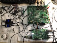
Now that I got a week to focus on development, rather than arguing with the golden ears, here's a quick update: Got the first Arta distortions measurements, using the AKD4499 reference board, an AK5572 board, and the XMOS-AUDIO-216 board.
Both the AK4499 DAC and the AK5572 ADC are in slave mode, running with the MCLK from the XMOS board reference clock, and BICK and LRCK generated by the XMOS chip. The XMOS code was modified to accomodate the AK4499 and AS5572 registers set and required settings. Got around -117dB loopback THD @1KHz, and -110dB THD+N both @48KHz sample rate. At higher sample rates, I can now confirm myself that the AK5572 has the same noise floor increase at high frequency as the majority of audio ADCs on the market, in all high sampling rate modes. So the AK5572 is clearly inferior to any SAR ADC available on the market.
The current XMOS chip generates the LRCK and BICK clock in software, based on the sample rate received from Arta. That's a lot of room for improvement here; currently working on integrating a programmable CDC925 PLL clock generator; the idea is to modify the code to send I2C commands to the clock generator, modifying on the fly the frac PLL and the output hardware dividers and generate an optimal clock structure, for each DAC/ADC mode, up to the max 192KHz sampling rate supported by the Thesycon/Microsoft driver.
Second in the TODO list is integrating a 20bit SAR ADC. Conversion from SPI to I2S is surprisingly difficult to do without using a FPGA (and even with a FPGA is non trivial, if it is to cover all I2S modes). That's because of the I2S specification which requires a one BICK clock delay between LRCLK and DIN/DOUT. It is much simpler though, if it is to cover only the Left Justified mode, since the same I2S specification states that DIN/DOUT should be "valid on the rising edge of BCLK following the falling edge of LRCLK". There is a good TI white paper on this conversion http://www.ti.com/lit/an/slaa449a/slaa449a.pdf and this is likely what was mentioned in this posting regarding a new 20bit R-2R DAC from TI https://www.diyaudio.com/forums/ven...1001-20-bit-2r-precision-dac.html#post6087981 Not sure yet how to approach this conversion issue, to restrict the conversion to Left Justified, and generate the LRCK in hardware, or to go the FPGA route (much more elegant, but hard to justify the cost of a FPGA chip for this fuctionality only). There is a 3rd route, to process the conversion in the XMOS chip software, but this is a hardcore task, not sure if I'm ready for it (and not sure if the results will be good enough to justify the effort).
I'll update here from time to time... still far from starting designing a board... need to experiment and then make the architectural decisions about the above issues.
There is a 3rd route, to process the conversion in the XMOS chip software, but this is a hardcore task, not sure if I'm ready for it (and not sure if the results will be good enough to justify the effort).
If you use the XMOS Reference Design, find in audio.xc the lines:
Code:
   #ifndef CODEC_MASTER
                /* LR clock delayed by one clock, This is so MSB is output on the falling edge of BCLK
                 * after the falling edge on which LRCLK was toggled. (see I2S spec) */
                /* Generate clocks LR Clock low - LEFT */
                p_lrclk <:0x80000000;
replace 0x80000000; to 0xFFFFFFFF;
also find:
Code:
            #ifndef CODEC_MASTER
                /* Clock out data (and LR clock) */
                p_lrclk <: 0x7FFFFFFF;
                doI2SClocks(divide);
            #endif
and replace 0x7FFFFFFF to 0x00000000;
You will get Left Justify.
If you use the XMOS Reference Design, find in audio.xc the lines:
Code:#ifndef CODEC_MASTER /* LR clock delayed by one clock, This is so MSB is output on the falling edge of BCLK * after the falling edge on which LRCLK was toggled. (see I2S spec) */ /* Generate clocks LR Clock low - LEFT */ p_lrclk <:0x80000000;
replace 0x80000000; to 0xFFFFFFFF;
also find:
Code:#ifndef CODEC_MASTER /* Clock out data (and LR clock) */ p_lrclk <: 0x7FFFFFFF; doI2SClocks(divide); #endif
and replace 0x7FFFFFFF to 0x00000000;
You will get Left Justify.
That was not the problem. The problem is converting SPI to I2S for all I2S possible formats (including Left Justified).
If you have a solution for converting SPI to I2S by software in the XMOS core (or tile) I am all ears.
Attached, the experimental setup (ADC + XMOS, AK4499 DAC reference board didn't fit in the pic, it's huge) and the ARTA loop measurements. -116dB THD @1.234KHz and about -112dB THD+N. Both at 0dBFS which is 10Vpp analog.
Note the point to point clocks wiring, this is a slap in the face to those preaching the MCLK, etc... clock criticality, audible differences between NDK and Crystek, the need for 1pS jitter, clean, etc..., it's hard to imagine a worse clock distribution (both for signal and ground return), though the numbers above are beyond any audibility thresholds. They will of course go down at least 3dB and the spurious noise grass will vanish when using a PCB.
ARTA works perfectly fine, so does RAW, but a trial version of SpectraPlus does not, it doesn't see the XMOS board in the hardware configuration, no idea why.
Attachments
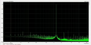
syn08, I think you should make the separate measurement of ADC and DAC, because on this picture you cannot know who produce this harmonics.
To do this you need anlogue oscillator with very low THD ("victor's" , or something else, discussed n the nearby threads
P.S. SpectraPlus in previous version has not very good ASIO, which not works with Thesycon driver, so need to use no-ASIO and to set sample rate and resolution the same as in Windows. In the last version it works.
Try also japan free software WaveSpectra, it works with ASIO very good and up to 384kHz.
If Syn is using the AKD4499 board then I think it's pretty safe to say the bottleneck here is the ADC.
In terms of raw distortion figures the 4499 is quite a bit better than the 557x series especially when driven near 0dBfs.
I am assuming that the AK4499 evaluation board has been through testing by AKM to ensure datasheet performance.
In terms of raw distortion figures the 4499 is quite a bit better than the 557x series especially when driven near 0dBfs.
I am assuming that the AK4499 evaluation board has been through testing by AKM to ensure datasheet performance.
If Syn is using the AKD4499 board then I think it's pretty safe to say the bottleneck here is the ADC.
Yep, already confirmed by measuring independently the AK4499 reference board. Has -127 to -130dB THD @1KHz and -0.5dBFS. About 6dB worse THD+N but that includes the lack of board and wiring shielding.
Yep, already confirmed by measuring independently the AK4499 reference board. Has -127 to -130dB THD @1KHz and -0.5dBFS. About 6dB worse THD+N but that includes the lack of board and wiring shielding.
Any way, you may use a Notch (-40..-50dB only) to isolte the ADC THD... look at on the forum and may latest RME ADI 2 Pro using the new AKM4493.
Hp
Any way, you may use a Notch (-40..-50dB only) to isolte the ADC THD... look at on the forum and may latest RME ADI 2 Pro using the new AKM4493.
Not sure what you are suggesting? Anyway, AK4499 is newer (and much better) than the AK4493.
No need to isolate the ADC THD, I tested the AK4499 independently with my Rohde UPD, the equivalent (in performance) to an AP System 2, and verified the results against a Panasonic VP-7722 (no relevant differences found).
The AP, UPD, VP-7722 already uses a Notch for measurements.
Using your AKM 55xx ADC & ARTA (or any else) requires a notch (minimal 40..50dB notch), so the ADC gets 40..50 dB lower full scale and this would lower/skip ADC THD and you would measure the DAC THD (only). The THD added of the Notch should be known 😀
Hp
The AP, UPD, VP-7722 already uses a Notch for measurements.
Using your AKM 55xx ADC & ARTA (or any else) requires a notch (minimal 40..50dB notch), so the ADC gets 40..50 dB lower full scale and this would lower/skip ADC THD and you would measure the DAC THD (only). The THD added of the Notch should be known 😀
With notching there's not much need to go for the latest and fanciest ADC/DAC. The fun is to push the THD under -120dB before notching 😀.
A fundamental frequency tracking notch has to be an analog subsystem, and that's not something for the faint hearts at these levels. In fact, I have no idea how to implement such an analog notch with anything like a known/controlled/reproducible distortion performance. I would think it makes much more sense to push the digital performance to -120dB, then apply notching to a set of predefined fixed frequencies, using a passive Twin-T (for example), when the need to measure -140dB distortions or lower occurs.
What we really need is an updated audio ADC based on the 5578 series. Pushing 130dBA SnR with better than 120dB distortion at all sampling frequencies and a flat noise floor.
We know the 5397 can do the flat noise so that's not an unreasonable demand. Adopting a parallel channel architecture eases the single channel noise requirements and should hopefully provide benefits towards harmonic distortion.
What I do wonder is if the typical 5V analogue supply is a limit to performance that could be significantly improved upon if 9 or 12V rails were used. It would certainly allow for a higher baseline noise if the full-scale signal amplitude were higher. Easing the front end design and presumably the input section of the ADC.
If AKM have decided that the AK4499 was worth it then an ADC counter part would seem a logical step forward too. While AKM might sell more 4499s to consumers the 557x series are very popular in high end music recording applications. I'd imagine an updated version would be just as popular, if the price isn't obscene.
- Home
- Design & Build
- Equipment & Tools
- ADCs and DACs for audio instrumentation applications