I was researching surface finish and stiction and downloaded this research paper via Harvard. Plan is to build a test rig to measure stiction of the carriage on the rail. I have a spare set of polished carbide rods 100mm then add a textured finish on the rail with wet&dry of various grades.
Not sure how I will proceed with the measurement, I have a set of calibration weights with trim weights to 30mg. I will probable use Carlo's method as it eliminates the drag on pulleys............
I'm not sure that the content of the research paper is appropriate for the surface finish of the rods. The paper is dealing with the effects of surface finish on sliding friction. The wheels do not slide on the rods. They roll. When I first got my carbide rods they had a relatively rough surface. Rolling resistance reduced significantly with polishing.
Niffy
Hi Chris,
I look forward to seeing what you come up with. I never tried my sapphire vees with steel pivots, only tungsten carbide. It will be interesting to see how they perform.
Niffy
I look forward to seeing what you come up with. I never tried my sapphire vees with steel pivots, only tungsten carbide. It will be interesting to see how they perform.
Niffy
smoothness - stiction: a molecular attraction can take place when the surfaces are so smooth as to make a really direct contact, eliminating the air film that always stands between solids.
Just a curiosity in our situation, but for larger surfaces instead it is surprising: once a client, a textile machinery industry, proudly showed me a sample of that surfaces
Van der Waals force - Wikipedia
intermolecular bonding - van der Waals forces
etc
Just a curiosity in our situation, but for larger surfaces instead it is surprising: once a client, a textile machinery industry, proudly showed me a sample of that surfaces
Van der Waals force - Wikipedia
intermolecular bonding - van der Waals forces
etc
So I bought a 5x200mm rod of these.
K10 Solid Cemented Carbide Tungsten Steel Round Bar Rods L: 10/20cm D: 2-10mm AU | eBay
And I got one that's "almost" straight and "almost" even 😕
According to K10 tolerance for a 5mm rod the diameter should be within
+0.048/-0mm. There's no mention of "straightness", and it's not. Is this what I should have expected ?
I have hand polished it for a few hours going from this:
To 1000/2500 grit wet paper and now it looks fairly decent, I wouldn't call it straight though.
Rolling it over a polished granit plate with backlight I would say it's of by ~0,05-0,1mm.
I'm planning to use it anyway, maybe I can straighten it some during assembly.
K10 Solid Cemented Carbide Tungsten Steel Round Bar Rods L: 10/20cm D: 2-10mm AU | eBay
And I got one that's "almost" straight and "almost" even 😕
According to K10 tolerance for a 5mm rod the diameter should be within
+0.048/-0mm. There's no mention of "straightness", and it's not. Is this what I should have expected ?
I have hand polished it for a few hours going from this:
An externally hosted image should be here but it was not working when we last tested it.
To 1000/2500 grit wet paper and now it looks fairly decent, I wouldn't call it straight though.
Rolling it over a polished granit plate with backlight I would say it's of by ~0,05-0,1mm.
I'm planning to use it anyway, maybe I can straighten it some during assembly.
Last edited:
I had the same problem with straightness. I bought 4 and the worst was 0.34mm out the best 2 were less than 0.1mm.
I figured they would straighten if I milled a pocket in the rail that the rods were a interference fit and clamp them with epoxy.
I figured they would straighten if I milled a pocket in the rail that the rods were a interference fit and clamp them with epoxy.
Hi Warrjon,
Looking good. I'm really interested to see how you make your height, rail leveling and LTA adjustments. Does the arm lock in place once in position and is it on linear bearings?
Niffy
Looking good. I'm really interested to see how you make your height, rail leveling and LTA adjustments. Does the arm lock in place once in position and is it on linear bearings?
Niffy
Hi Niffy.
The arm will lock in the forward position with neodymium magnets. I haven't machined the pockets for these yet. The bridge slides on 12mm industrial (close tolerance) linear bearings
Rail leveling - the 2 aluminium blocks at the side will hold the rail and have brass inserts pressed in. The uprights have an 8mm linear shaft. My boring head is not small enough so I am waiting for a reamer to make the hole in the brass for the shaft. In front of the brass I will tap a hole for a threaded shaft that will come out the top with a knob each side to raise and lower the rail.
Attachments
Last edited:
Hi Warrjon,
Just to make sure I've got this straight. You have a separate height adjuster at each end of the rail. To change the height of the rail you adjust both ends by the same amount. To adjust the slope of the rail you adjust just one end. Once you have the height and slope just right is there a separate lock to prevent that setting from changin? .
Do you adjust LTA by rotating the rail about one of the pillars or do you limit how far the rail slides on one or both of the bases?
Niffy
Hi Warren, for me instead is not clear what the upper beam is used for. Wouldn't the rail itself be enough for rigidity? Or, being the LT separated from the plinth/platter a substantial mass is needed for grounding the resonances?
carlo
Meanwhile - excellent workmanship, from what I see
carlo
Meanwhile - excellent workmanship, from what I see
I had the same problem with straightness. I bought 4 and the worst was 0.34mm out the best 2 were less than 0.1mm.
I figured they would straighten if I milled a pocket in the rail that the rods were a interference fit and clamp them with epoxy.
So mine where as expected then 😎 Well it looks fairly decent after some
work but I ordered these as an alternative anyway.
Precision Shaft 6mm h6 Hardened and Grinded - Rod Length 1 Meter (1000mm) | eBay
If the first one works just fine they may come in handy in some other project 🙂
Hi Warren, for me instead is not clear what the upper beam is used for. Wouldn't the rail itself be enough for rigidity? Or, being the LT separated from the plinth/platter a substantial mass is needed for grounding the resonances?
carlo
Meanwhile - excellent workmanship, from what I see
Building the support structure for the rail in this way does have the potential to work extremely well. A bridge structure is inherently much more rigid than a cantilever.
I seriously considered building my arm in this fashion. I didn't for two main reasons.
I couldn't find an elegant way of implementing the adjustments into the bridge structure. This is why I'm very keen to see how Warren tackles this problem. Building the adjustments in a cantilevered structure is much simpler.
The bridge requires a large plinth to be mounted to. A large part of the design of my deck is based around making the sub chassis small. Making the sub chassis smaller has the same benefits as making the armtube shorter, better resonance control. Warren's SP10 mounted in his large plinth has lots of realestate onto which to mount the bridge structure.
Niffy
Hi Niffy,
Yes each end of the rail is adjustable independently for VTA via a knob on top of the bridge. LTA will be adjustable by moving the base of the bridge where it bolts to the plinth. There will adjustment in the rail itsself where it attaches to the posts to level the rail. Basically loosen the bolt on the rail and adjust one side till the rail is level then tighten.
I was going to use 8mm linear bearings for VTA but decided against this because I want to be able to lock the VTA with a set screw which I can do with the bush. So the rail will be mechanically grounded to the upright.
Hi Carlo,
The upper beam is for rigidity and to hold the VTA adjustment screw and linear shaft. I don't think the rail its self is enough for rigidity because of its length 400mm.
Warren's SP10 mounted in his large plinth has lots of realestate onto which to mount the bridge structure.
Niffy
That plinth was built specifically to take this arm. I pondered a lot about it before I started construction.
I could not work an elegant way to incorporate LTA into the rail so I will just have large holes in the plinth so the bridge base can move back and forth.
I'm still with H. Ford "if it isn't there, it can't... resonate" - maybe making a stiffer rail. And still with the ideas of the last century - tonearm + platter is a single system, not two.
Beam vs cantilever: although it must be twice as long, from a static point of view a beam is evidently better, but two paths for the resonances? really i can't answer, and that seems the only problem, not to keep a few grams raised.
carlo
Beam vs cantilever: although it must be twice as long, from a static point of view a beam is evidently better, but two paths for the resonances? really i can't answer, and that seems the only problem, not to keep a few grams raised.
carlo
Last edited:
Hi all,
I've been having fun doing a bit more experimentation with the behaviour of my bearings.
When I was using ballrace bearings you could see that the motion of the arm with eccentric records was;
Move to the left
Stop
Pause
Lurch to the right
Continue moving to the right
Stop.
Pause.
Lurch to the left.
The issue here is the pause lurch.
Whilst moving the bearing is in dynamic friction. When it reaches the end of its movement it stops and drops into static friction. It then pauses until the side force is great enough to overcome the static friction. It then moves. As soon as it starts moving it is back in dynamic friction. Dynamic friction is much lower than static friction but the side force is still high so the carriage lurches. This is the classic problem of stiction, constantly cycling between dynamic and static frictions.
The limiting factor here is static friction. The greatest force, and therefore cantilever defection, occurs just as the side force is great enough to overcome static friction.
As static friction was the limiting factor for the ballrace bearings I assumed it would be for the pin bearings as well. So when I built my bearing test rig I designed it to only measure static friction. If the limiting factor for my current bearings is also static friction then they should also show the pause-lurch behaviour, just to a much lower level.
As the cantilever defection is so small, even under the high magnification of the videos, it is not possible to see the nature of the movement of the arm. Another approach is necessary.
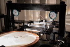
As I am only interested in friction for this experiment I chose a record with only minimal eccentricity so that inertial effects would be minimised but frictional effects would not. This also means that the amount of arm movement would be less and more difficult to see. To overcome the problem of seeing the motion of the arm in detail I used the following technique.
I taped a fine needle to the top of one of the wheels so that it is sticking straight up. Now as the arm moves back and forth and the wheel rotates the tip of the needle will move a lot more, amplifying the motion of the arm. This still isn't enough to clearly see the detail of the arm motion. By shining a light on the needle a small reflection spot occurs. As the needle moves the reflection spot moves up and down the needle. By watching this spot you can see the detail of the movement of the arm.
Here's the interesting point. The movement of the spot is smooth showing no signs of pause-lurch behaviour. This would indicate that the bearing is not dropping to static friction at the ends of its movement but is permanently staying in dynamic friction.
There are a couple of possible reasons why the bearings aren't dropping into static friction. As the movement of the eccentricity is basically a smooth sine wave the point at which the arm becomes stationary is a mathematical point of infinitely short duration. The materials of the bearings don't have time to settle before they're moving again. Secondly, the bearing is designed to be a mechanical ground. Therefore it is constantly transmitting vibrational energy. This energy could be preventing the bearing from settling preventing it from dropping to static friction.
Unfortunately I never measured dynamic friction so I don't know great this is compared to static. It is considerably less. When measuring the static friction, as soon as the pendulum pushed the carriage hard enough to move it it would roll along way. I guess dynamic friction is somewhere in the region of 20-30% of static. As my deck is set up so nicely at the moment I don't feel inclined to take it to bits to work this out.
If the bearings are permanently staying in dynamic friction then this would explain why the cantilever deflections observed seemed so much less than expected. This would also mean that bearing friction will not be the main source of LTA error. In this case bearing friction could be on a par with inertia with groove angle being the predominant cause for most records.
Niffy
I've been having fun doing a bit more experimentation with the behaviour of my bearings.
When I was using ballrace bearings you could see that the motion of the arm with eccentric records was;
Move to the left
Stop
Pause
Lurch to the right
Continue moving to the right
Stop.
Pause.
Lurch to the left.
The issue here is the pause lurch.
Whilst moving the bearing is in dynamic friction. When it reaches the end of its movement it stops and drops into static friction. It then pauses until the side force is great enough to overcome the static friction. It then moves. As soon as it starts moving it is back in dynamic friction. Dynamic friction is much lower than static friction but the side force is still high so the carriage lurches. This is the classic problem of stiction, constantly cycling between dynamic and static frictions.
The limiting factor here is static friction. The greatest force, and therefore cantilever defection, occurs just as the side force is great enough to overcome static friction.
As static friction was the limiting factor for the ballrace bearings I assumed it would be for the pin bearings as well. So when I built my bearing test rig I designed it to only measure static friction. If the limiting factor for my current bearings is also static friction then they should also show the pause-lurch behaviour, just to a much lower level.
As the cantilever defection is so small, even under the high magnification of the videos, it is not possible to see the nature of the movement of the arm. Another approach is necessary.
As I am only interested in friction for this experiment I chose a record with only minimal eccentricity so that inertial effects would be minimised but frictional effects would not. This also means that the amount of arm movement would be less and more difficult to see. To overcome the problem of seeing the motion of the arm in detail I used the following technique.
I taped a fine needle to the top of one of the wheels so that it is sticking straight up. Now as the arm moves back and forth and the wheel rotates the tip of the needle will move a lot more, amplifying the motion of the arm. This still isn't enough to clearly see the detail of the arm motion. By shining a light on the needle a small reflection spot occurs. As the needle moves the reflection spot moves up and down the needle. By watching this spot you can see the detail of the movement of the arm.
Here's the interesting point. The movement of the spot is smooth showing no signs of pause-lurch behaviour. This would indicate that the bearing is not dropping to static friction at the ends of its movement but is permanently staying in dynamic friction.
There are a couple of possible reasons why the bearings aren't dropping into static friction. As the movement of the eccentricity is basically a smooth sine wave the point at which the arm becomes stationary is a mathematical point of infinitely short duration. The materials of the bearings don't have time to settle before they're moving again. Secondly, the bearing is designed to be a mechanical ground. Therefore it is constantly transmitting vibrational energy. This energy could be preventing the bearing from settling preventing it from dropping to static friction.
Unfortunately I never measured dynamic friction so I don't know great this is compared to static. It is considerably less. When measuring the static friction, as soon as the pendulum pushed the carriage hard enough to move it it would roll along way. I guess dynamic friction is somewhere in the region of 20-30% of static. As my deck is set up so nicely at the moment I don't feel inclined to take it to bits to work this out.
If the bearings are permanently staying in dynamic friction then this would explain why the cantilever deflections observed seemed so much less than expected. This would also mean that bearing friction will not be the main source of LTA error. In this case bearing friction could be on a par with inertia with groove angle being the predominant cause for most records.
Niffy
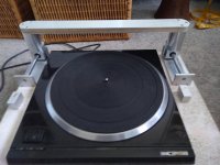
Here is what I did for one of my arms. I designed it with 4 of 8 mm long slots on both side under the set screws so I don’t have force the bridge piece up or down. In some of cases, the difference of bridge on both side may be too large. Then, you need the mechanism I designed.
Warrjon,
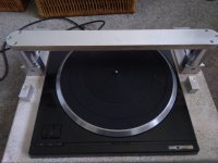
It is a great job you did! However, the bridge should be on the same plane as the table platform. If so, you also need to think the balance of the table since the bridge looks pretty heavy from the photo. You may need counter balance on the opposite side of table.
Warrjon,
It is a great job you did! However, the bridge should be on the same plane as the table platform. If so, you also need to think the balance of the table since the bridge looks pretty heavy from the photo. You may need counter balance on the opposite side of table.
Attachments

Niffy,Hi all,
Secondly, the bearing is designed to be a mechanical ground. Therefore it is constantly transmitting vibrational energy. This energy could be preventing the bearing from settling preventing it from dropping to static friction.
Niffy
I think you are onto something with the vibration theory. Makes me think of the effect of dithering the least significant bit in digital and adding a bias tone in analog tape recording to 'shake up' the magnetic particles. It would be interesting to compare the results of testing an off-center record with a modulating signal that provides the bearing with vibration and then doing the same test with the stylus just circling in the runout groove where there should theoretically be no vibration. If the stiction reappears in the runout groove then that would re-inforce the vibration theory. I've also wondered if record warps or wobbly platters might have a similar counter-intuitive mitigating effect on bearing friction in unipivots.
Ray K
It is a great job you did! However, the bridge should be on the same plane as the table platform. If so, you also need to think the balance of the table since the bridge looks pretty heavy from the photo. You may need counter balance on the opposite side of table.
Not sure what you mean by the bridge needs to be on the same plane as the table platform.
When the arm is in the play position the whole bridge is almost in the centre of the TT so fore and aft balance will not be an issue. The TT is sat on a board with 4 of these under it and only 2 springs in each. I can add springs to level the TT, then final level with adjustable feet on the TT.
4pcs CD Player AMP Speaker Turntable Isolation Feet Stands Spring Machine Mats-in Speaker Accessories from Consumer Electronics on AliExpress
I like how you mounted the rail below the cross bar what did you make the rail cross bar from. Maybe aluminium tube filled with expanding foam........
Warrjon,
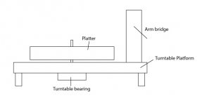
Please see the drawing. I meant that the bridge should be on the same platform as the bearing of the turntable. I expanded the platform on my turntable so the bridge is located on the same platform. In other words, it should be on the same platform as you normally mount your regular pivot arm.
Please see the drawing. I meant that the bridge should be on the same platform as the bearing of the turntable. I expanded the platform on my turntable so the bridge is located on the same platform. In other words, it should be on the same platform as you normally mount your regular pivot arm.
Attachments
- Home
- Source & Line
- Analogue Source
- DIY linear tonearm