Anyone have a source for the 5pF Cap, C9, for the pearl2. What are you using , Poly, ceramic,etc?
Got some CAT5 cable ? -- twist together about 4 inches, 10cm -- should be the puffs you need. (CAT5 is 1.3pF/inch or 52pF/meter).
Ground loop breaker
Which may, or may not be up to code if you aren't in the States. (but it works over here!)
Ground loop breaker
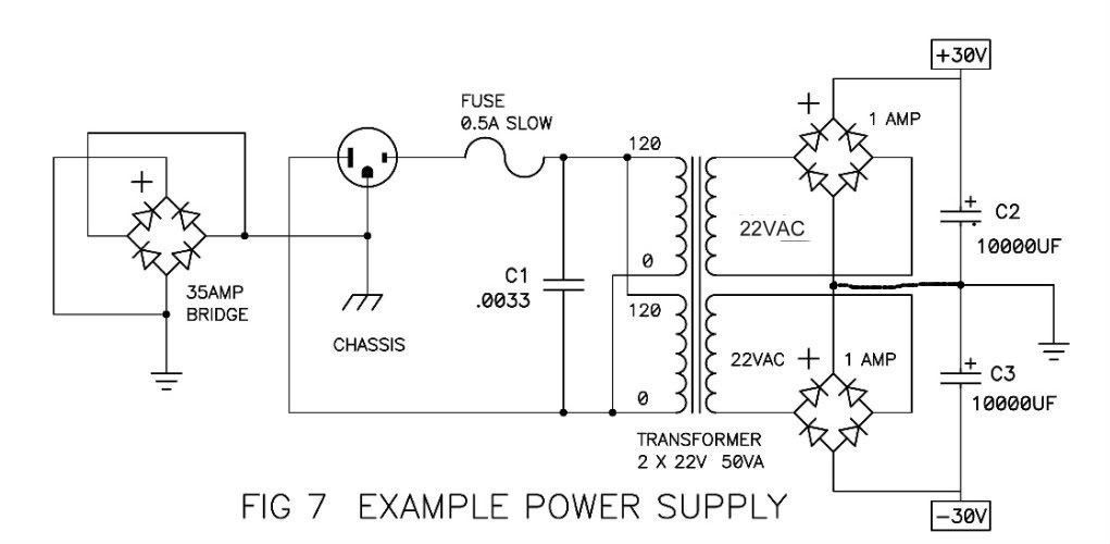
Oh wow. Right now I'm having an issue with gound loop hum in a tube preamp. This might help me. I see that one end is connected to the inlet ac connector's ground, which is connected to the chassis. but what is the other end connected to? I mean what else is there?
thanks. ive been reading it all morning and I plan to do this in my DIY phono and my pre amp. still two things unclear:
1 - why does it have to be 35A? does 25A not function properly in this application as ground loop breaker?
2 - I guess the answer to my original question is: to the signal ground?
1)25A would work fine. I suspect the 35A was specked because there is a big box of them on the shelves of the parts room at Pass Labs. You wouldn’t want to go much smaller however, as the bridge must carry any AC fault current for safety.
2) the breaker connects from the chassis/IEC safety earth on one side and the PSU ground on the other. Look at the 2 different ground symbols in the schematic in the article.
2) the breaker connects from the chassis/IEC safety earth on one side and the PSU ground on the other. Look at the 2 different ground symbols in the schematic in the article.
I've wondered why the Pearl 2 PS has this diode bridge, while the F5 has a thermister in that spot.
Thanks, great article! Every DIY'r should read it.
I especially liked the part about electrocution... seems to be an issue to take care of [emoji850]
I like uncle Rod's comment:
"The result of fatal electrocution is that you will no longer be able to enjoy the hi-fi that you have spent so much time and money putting together"😀
"The result of fatal electrocution is that you will no longer be able to enjoy the hi-fi that you have spent so much time and money putting together"😀
Has any one used single package bridge rectifiers in PSU builds vs 4 separate diodes , ie KBPC3510W-G. Any disadvantages, audio degradation?
I have used single package bridge rectifiers in PSU builds for audio power amps. I bought the ones with "Fast On" blade connectors and diodes rated 35 amps, 1000 volts. Mouser part number 512-GBPC3510
No complaints about the sound.
No complaints about the sound.
Hello members,
I use exactly the same bridge-rectifier together with a CL-60 thermistor for
building my ground-loop-breakers.
I use them in all of my DIY- Pass-poweramps.
Sometimes I did it with 2 single Diodes (direction against each other - paralleled together with a paralleled resistor around 10 Ohms) in my preamps, active crossovers,... with lower power consumption.
Works beautiful. Also in Germany with 230V/50Hz.
But hum or hiss can also have other reasons! 🙄
But often there are groundloops. My experience.
Greets
Dirk
Attachments
- Home
- Amplifiers
- Pass Labs
- Building a Pearl 2