The best fan I ever installed was a quiet Pabst one. It was over $100, but it really did the trick.
-Chris
-Chris
Hope everyone had a lovely Christmas!
Thanks for the comments on the fan.
Can't seem to find anything concrete on the cfm figure for the fan, but 100 cfm has been mentioned.
I have found a couple of ebm-papst fans
86cfm 36db
100cfm 39db
Yes they are £70 each, not cheap but I guess they will last!
The fan in the unit is a Torin TA450 115V but of course in the UK we run 230ishV, so not sure if the thing has been running hyper speed or something has been done to account for this voltage difference.
It looks like there is a rather large resistor of 300Ohm and 20W connected to the connector plate just near the mains cable 'in' area, and it looks like it is in the fan and temp sensors circuit but I have not worked the circuit out yet!
I can't see the amp being pushed hard, but you never know what it may be needed for, Yes at home I am likely to hear the fan even if at 36dB...
Anyone know the proper cfm specification figure?
Okay I am working out that the 300 Ohm resistor should be in circuit until the temp rises and then gets taken out the circuit, so fan starts off with the resistor and so is slower than full speed, and then when things warm up the resistor gets bypassed and so fan speeds up.
The 300 Ohm resistor measures 93 Ohm so guess than could be replaced ! and fan is going faster than it needs to when cool due to the lower than spec resistance.
The 300 Ohm resistor measures 93 Ohm so guess than could be replaced ! and fan is going faster than it needs to when cool due to the lower than spec resistance.
Okay I am working out that the 300 Ohm resistor should be in circuit until the temp rises and then gets taken out the circuit, so fan starts off with the resistor and so is slower than full speed, and then when things warm up the resistor gets bypassed and so fan speeds up.
The 300 Ohm resistor measures 93 Ohm so guess than could be replaced ! and fan is going faster than it needs to when cool due to the lower than spec resistance.
very easy and cheap
you can replace old BGW FAN circuit
with 12V FAN PWM temperature control
and 750B is not noisy anymore
Attachments
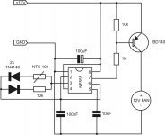
The fan runs @ 120 volts and when 230/240 volt power is selected the fan run off the 120 volt tap on the tx. The 300 ohm resistor was to let the fan run @ a slow (low noise) level and the thermal switches bypass the resistor for full speed fan.
Duke
Duke
Nmos - thanks for the handy suggestion but I am afraid my level of skill is only at the replace like for like status at the moment!
Duke - Wow thanks for the info.! I was going to order a 230v fan Monday morning. I have just checked out the 120v fans and their power consumption is way up compared to the 230v fans.
I shall have to have a look in side the case and see if there is a way of easily connecting the 230v fan! if not I shall go the for 120v and connect it in exactly the same way the old one is. Oh, and yes I will put in a new 300 Ohm resistor too.
Cheers 🙂
Hi Deaf Cat,
Just install the fan with one rated about the same, including voltage. The fan will run on a 120 VAC winding, so you won't have any problems. Now, if you decide to buy 220 VAC fans, you're now engineering this circuit on your own. Don't do that.
Duke sent you down the correct path. Take it.
-Chris
Just install the fan with one rated about the same, including voltage. The fan will run on a 120 VAC winding, so you won't have any problems. Now, if you decide to buy 220 VAC fans, you're now engineering this circuit on your own. Don't do that.
Duke sent you down the correct path. Take it.
-Chris
Cheers Chris!!
I did think.. okay just plug on the 230v winding... but, then... what happens to the resistor circuit..
So Thank You for the second Hint! - follow the correct path - much appreciated!!
115v ebm-papst on order 🙂
With the new 300 Ohm resistor I am hoping it will be quieter than the rated 42dB eeek!
Mind you I think anything will be quieter than the existing rattly old thing!
At least with like for like replacements if it is run hard at any point in its life it will not fry its self - which is of course rather important!
Many Thanks 🙂
I could acquire three BGW750 with Serial Numbers 80A0292, 80C0416, 80D0770.
5 out of 6 Amp Modules are labeled 9007-0751D and one 9007-0751C. See pictures here: Modules - Google Drive
I've recapped the modules as described earlier in this thread.
What I've noticed is that the 9007-0751C is different to the 9007-0751D, it seems to missing some modifications.
Does anyone know what these modifications are and if they are recommended?
Best wishes from Switzerland,
Marcel
You can probably look at the schematics here;
BGW 750 - Manual - Stereo Power Amplifier - HiFi Engine
Need to sign up for an account to download files, great resource.
BGW 750 - Manual - Stereo Power Amplifier - HiFi Engine
Need to sign up for an account to download files, great resource.
We should ask Diy Member Audio1Man
about latest schematic updates from 750B/C 1978 - 1986
he was BGW Engineer < 1986
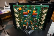
I find other modification have big
NON Polar Capacitor parallel with Elektrolyt Condensator after 100 OHM resistor from Op AMP Pin 6 output
Any Idea whats the benefit to add parallel NoN Polar ..look picture?
about latest schematic updates from 750B/C 1978 - 1986
he was BGW Engineer < 1986
I find other modification have big
NON Polar Capacitor parallel with Elektrolyt Condensator after 100 OHM resistor from Op AMP Pin 6 output
Any Idea whats the benefit to add parallel NoN Polar ..look picture?
Attachments
Last edited:
I could acquire three BGW750 with Serial Numbers 80A0292, 80C0416, 80D0770.
5 out of 6 Amp Modules are labeled 9007-0751D and one 9007-0751C. See pictures here: Modules - Google Drive
I've recapped the modules as described earlier in this thread.
What I've noticed is that the 9007-0751C is different to the 9007-0751D, it seems to missing some modifications.
Does anyone know what these modifications are and if they are recommended?
Best wishes from Switzerland,
Marcel
3 Capacitor and 1 resistor is missing in D revision
please check schematic which parts missing und give feedback.
Did you have difference sound in Fullrange between D and C Revision ?
Last edited:
This type of amplifier works quite well with rail switches if you follow a few simple precautions. Run the VAS at full supply. Use the full complementary output. Earlier versions with the RCA 2N6259 outputs will not work with rail switches - even if you switch to a faster output like the 15024. It oscillates audibly every time the rail switches and it cannot be fixed. Stick in PNPs in the bottom half and the problem magically goes away.
I think with Class TD there is no Oscillation
Class TD have 1 Rail same Class AB, rail is variable for example from 20 to 100 V DC
Class TD have 50 - 100 Kkz Switching frequency.
I think Class TD should working, At any Moment,, regardsless of what the output of the amplifier is, the power supply will always be 6V above the output signal
When have SMPS for Quasicomplementary Output stage, there is no Oscillation, why should variable SMPS / Class TD not working for Quasicomplementary Output stage, ther will be no spikes problem compare to Class H
Most SMPS working 50 - 100 Kkz Switching frequency.
Last edited:
Class TD might work for a QC output stage. As long as the tracker’s output impedance is very LOW at high frequency the amp will be stable. Most implementations have a smoothing cap of a couple uF, which would do the trick. In a class H the power supply impedance goes high during the transition from low to high rail. This effectively removes the power supply bypassing for a microsecond or so, and a compound triple just can’t handle that whereas the EF3 can. You could add a cap to ground, but that stresses the rail switch and reduces efficiency. The LC filter on the class TD has both a controlled rate of rise of current, and low output Z at high frequency. Could be worth a try.
Class TD might work for a QC output stage. As long as the tracker’s output impedance is very LOW at high frequency the amp will be stable. Most implementations have a smoothing cap of a couple uF, which would do the trick. In a class H the power supply impedance goes high during the transition from low to high rail. This effectively removes the power supply bypassing for a microsecond or so, and a compound triple just can’t handle that whereas the EF3 can. You could add a cap to ground, but that stresses the rail switch and reduces efficiency. The LC filter on the class TD has both a controlled rate of rise of current, and low output Z at high frequency. Could be worth a try.
The Reason for QC BGW 750B Class TD is
Class D > 90 V DC Fullrange 250 - 350 khz have big Switching losses and generate al lot of heat also ar IDLE
Class D > 90 V DC need to be bridged for High Quality Audio and cold running
Do you remember Class D QSC PL380 ? Very hot at Idle running 160 V DC Halfbridge
Class TD can working easy with 160 V DC Rail and no need to be bridged
Class TD will running cold with 160 V DC Rail at Idle without switching loss isssues, efficiency similar Class D
Quasicomplementary Output stage with SMPS N Channel Switching Power Mosfets or IGBTs can do the job with ease, only 20 khz is max Frequency.
Class TD might work for a QC output stage. As long as the tracker’s output impedance is very LOW at high frequency the amp will be stable. Most implementations have a smoothing cap of a couple uF, which would do the trick. In a class H the power supply impedance goes high during the transition from low to high rail. This effectively removes the power supply bypassing for a microsecond or so, and a compound triple just can’t handle that whereas the EF3 can. You could add a cap to ground, but that stresses the rail switch and reduces efficiency. The LC filter on the class TD has both a controlled rate of rise of current, and low output Z at high frequency. Could be worth a try.
Lets try it, Class TD have benefits with High Voltage > 100 V DC compare to Class D and no need to be bridged
Class TD doesn’t need ridiculous SOA, since the VCE (or VDS) on the active device is low when conducting high current. There may not be any need for QC or even a mosfet output stage - devices like C5200/A1943 may be used. The rail switches or modulator of course may be same sex mosfets, but that doesn’t make the amp QC or create the problems that the compound triple output device does.
Class TD doesn’t need ridiculous SOA, since the VCE (or VDS) on the active device is low when conducting high current. There may not be any need for QC or even a mosfet output stage - devices like C5200/A1943 may be used. The rail switches or modulator of course may be same sex mosfets, but that doesn’t make the amp QC or create the problems that the compound triple output device does.
IF QC in Classs TD not work. I will give up or will using Lateral P/N Mosfets
I not like BJT
Lets try soon
BGW 750C Refurbishment - SEEKING GUIDANCE
Hello to the forum!
First time poster, long time lurker here.
After searching related threads and posts on this forum it seems this is the correct thread to post my query regarding servicing my BGW 750C amplifier.
Apologies, this will be a lengthy and detailed post, I wish to give as much information as I can that will be useful, I hope this is okay!
Firstly I wish to state that I have thoroughly read through all previous posts in this thread and other threads that relate to the questions I have formulated. I appreciate this particular thread, spanning over many years holds a wealth of knowledge and advice from true BGW experts. It is very sad that DJK passed, his knowledge was second to none, and it continues to help to this day.
My scenario is as follows:
In short, I have just acquired a 'working' BGW 750C. I have specific questions related to its refurbishment and I wish to seek some guidance before purchasing parts. For the record, I am based in the UK.
Initial Assessment:
The amp indeed turns on, and remains on indefinitely without issue. The DC offset for LEFT and RIGHT channels measured 05.4 and 05.0 respectively. Given these figures I went ahead and connected the amp to speakers and fed it signal (This particular amp has Sowter input transformers allowing balanced connection). Both channel pots work and both channels pass audio without any obvious distortion, buzz or other artefacts. The first issue I note is that since turning the amplifier on the right channel 'clip' LED has remained illuminated.
Initial internal visual damage assessment:
The amp is extremely dirty and dusty inside but I can initially confirm that there aren't any components in the output stages or in the chassis that visually appear to be in seriously bad condition.
Notes on components:
My first observation is that there are a couple of RCA brand NPN output transistors in the right output module, the rest are all Motorolas. My second is that there are some component differences, one module has 3 ceramic disc caps rather than dipped mica, and a blue 50v mylar cap (C21 on schematic). The other module has the correct orange 100V mylar cap but a different pair of electrolytics (C11 & C12) which are 20uF 150V.
Proposed plan of action:
It appears there are no serious or debilitating issues to immediately address with this amplifier so I will go ahead and perform a general service and replacement of ageing and mismatched components. After much reading of this thread and others on the subject I have compiled an initial set of jobs to perform:
1. Remove transistors, PCB, and clean heat sink.
2. Replace old transistors with new MJ21195G and MJ21196G type, which I will purchase from Digi-Key. Also replace Mica insulators and apply new thermal Silicone grease.
3. Replace electrolytic caps C11 & C12 with Nichicon 22uF 100v, bypassed with Vishay 0.01uF film.
4. Replace electrolytic C3 with.. ?
5. Replace Tantalum cap C1 with 10uF 100v polypropylene bypassed with Vishay 0.01uF film.
6. Install 47µF 160V electrolytics in parallel with the main filter caps to tighten bass reproduction.
7. Install a new 115v fan.
Questions:
Through research I have compiled the above list of upgrades to make to my 750C, but I wish to ask for some input and guidance on a few things:
1. Should I change the output transistors??! I have read that because the original transistors are Hometaxial slow, and new parts are fast so the frequency compensation needs to be addressed? I can say that I have no experience at all in making frequency compensation adjustments. Could I be shown how to do it or would I require advance knowledge and specific measurement tools?
2. The electrolytic cap C3 is 50uF 12V, I cannot find a modern part to replace it. Any suggestions?
3. Clip light. Currently the right channel clip light on my 750 stays on which I have read is driven from overload of the LM318. I will check components C9 and C2 for leakage but any other possible reason for this occurrence?
Any other comments or input on my proposed refurbishment would be greatly appreciated. I would like to feel confident I am making the right choices before undertaking this project.
Thanks!
C.E
Hello to the forum!
First time poster, long time lurker here.
After searching related threads and posts on this forum it seems this is the correct thread to post my query regarding servicing my BGW 750C amplifier.
Apologies, this will be a lengthy and detailed post, I wish to give as much information as I can that will be useful, I hope this is okay!
Firstly I wish to state that I have thoroughly read through all previous posts in this thread and other threads that relate to the questions I have formulated. I appreciate this particular thread, spanning over many years holds a wealth of knowledge and advice from true BGW experts. It is very sad that DJK passed, his knowledge was second to none, and it continues to help to this day.
My scenario is as follows:
In short, I have just acquired a 'working' BGW 750C. I have specific questions related to its refurbishment and I wish to seek some guidance before purchasing parts. For the record, I am based in the UK.
Initial Assessment:
The amp indeed turns on, and remains on indefinitely without issue. The DC offset for LEFT and RIGHT channels measured 05.4 and 05.0 respectively. Given these figures I went ahead and connected the amp to speakers and fed it signal (This particular amp has Sowter input transformers allowing balanced connection). Both channel pots work and both channels pass audio without any obvious distortion, buzz or other artefacts. The first issue I note is that since turning the amplifier on the right channel 'clip' LED has remained illuminated.
Initial internal visual damage assessment:
The amp is extremely dirty and dusty inside but I can initially confirm that there aren't any components in the output stages or in the chassis that visually appear to be in seriously bad condition.
Notes on components:
An externally hosted image should be here but it was not working when we last tested it.
An externally hosted image should be here but it was not working when we last tested it.
An externally hosted image should be here but it was not working when we last tested it.
An externally hosted image should be here but it was not working when we last tested it.
My first observation is that there are a couple of RCA brand NPN output transistors in the right output module, the rest are all Motorolas. My second is that there are some component differences, one module has 3 ceramic disc caps rather than dipped mica, and a blue 50v mylar cap (C21 on schematic). The other module has the correct orange 100V mylar cap but a different pair of electrolytics (C11 & C12) which are 20uF 150V.
Proposed plan of action:
It appears there are no serious or debilitating issues to immediately address with this amplifier so I will go ahead and perform a general service and replacement of ageing and mismatched components. After much reading of this thread and others on the subject I have compiled an initial set of jobs to perform:
1. Remove transistors, PCB, and clean heat sink.
2. Replace old transistors with new MJ21195G and MJ21196G type, which I will purchase from Digi-Key. Also replace Mica insulators and apply new thermal Silicone grease.
3. Replace electrolytic caps C11 & C12 with Nichicon 22uF 100v, bypassed with Vishay 0.01uF film.
4. Replace electrolytic C3 with.. ?
5. Replace Tantalum cap C1 with 10uF 100v polypropylene bypassed with Vishay 0.01uF film.
6. Install 47µF 160V electrolytics in parallel with the main filter caps to tighten bass reproduction.
7. Install a new 115v fan.
Questions:
Through research I have compiled the above list of upgrades to make to my 750C, but I wish to ask for some input and guidance on a few things:
1. Should I change the output transistors??! I have read that because the original transistors are Hometaxial slow, and new parts are fast so the frequency compensation needs to be addressed? I can say that I have no experience at all in making frequency compensation adjustments. Could I be shown how to do it or would I require advance knowledge and specific measurement tools?
2. The electrolytic cap C3 is 50uF 12V, I cannot find a modern part to replace it. Any suggestions?
3. Clip light. Currently the right channel clip light on my 750 stays on which I have read is driven from overload of the LM318. I will check components C9 and C2 for leakage but any other possible reason for this occurrence?
Any other comments or input on my proposed refurbishment would be greatly appreciated. I would like to feel confident I am making the right choices before undertaking this project.
Thanks!
C.E
Replacing old hometaxial outputs with modern ones has advantages and disadvantages. The usual good advice is to leave it alone if it’s working. If that is what you have they are pretty rugged and the amp was designed for them. That may or may not be what you have. Motorola never made them. If you have homo’s they are RCA because it’s their process. Homo’s and Epi’s should not be mixed, and it wouldn’t have come from the factory that way.
You may have original RCA drivers - which would be a triple-diffused type. They can drive either type of output. If yours is full complementary, they will be MJ15024/15025 or equivalent, regardless of who made them. When they finally started making the 15025, hometaxials were all but gone and prices of what you could get were through the roof.
The only times I would replace a working set of outputs is a) if some previous tech mixed types or only replaced the one that was blown and left the rest (now mis-matched), or b) I was dead set on converting a QC stage to full complementary. I converted one of my Phase Linears to complementary - but it had a bunch of mismatched outputs in it from at least 2 separate repairs. The other had the original FPL909’s in it so I left it alone.
- Home
- Amplifiers
- Solid State
- BGW 750B output modules