Quick question about mounting the mosfets: should there be some airspace between the top of the mosfet and the bottom of the PCB? I don't think they are currently touching, but they're mighty close. Wondering if I should add a spacer to raise up the PCB a bit...
Attachments
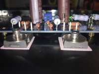
You have plenty of MOSFET leads extending above the PCB, raise it up a couple of mm's and ditch the round washers for proper heat sinks. Better clamping of the MOSFET to the primary heatsink and added fins for a buck or two.
had the same problem.... the 3mm spacers are too short... had to add a lot of washers between each spacer, and the PCB.
Thanks, elwood625 and Extreme_Boky!
Interesting about using small heatsinks to secure the mosfets. I don't think I've seen that before. I just looked back at the pictures of your build, elwood625, and see what you mean. Thanks for the suggestion.
Interesting about using small heatsinks to secure the mosfets. I don't think I've seen that before. I just looked back at the pictures of your build, elwood625, and see what you mean. Thanks for the suggestion.
I had to twist the first fin next to the PCB, 90' to get the heat sink to fit, pliers did the trick.Digikey and Mouser both sell.
Do you have a measurement when the amp is stressed, like 20KHz 20W in 8 ohm load?Distortion analysis, left channel is the first pic and right channel the second. Primarily an H2 amplifier, so I'll use my BZLS preamp to listen to the first music made. I plan on playing music on the amp the rest of this week and then substitute amp and preamp for the M2X with B1Korg preamp currently in my listening room.
Distortion analysis...
What load did you use for this?
What was the output voltage?
Elwood, can you hear hum in your speakers? There’s a lot of hash on the PSU side of that graph.
The distortion spectra (H2/H3 in relationship to fundamental) looks pretty darn good. Would like to see a shot where your 1K tone is at 0dBFS to see all the relationships to scale.
What is your load?
The distortion spectra (H2/H3 in relationship to fundamental) looks pretty darn good. Would like to see a shot where your 1K tone is at 0dBFS to see all the relationships to scale.
What is your load?
Elwood, can you hear hum in your speakers? There’s a lot of hash on the PSU side of that graph.
The distortion spectra (H2/H3 in relationship to fundamental) looks pretty darn good. Would like to see a shot where your 1K tone is at 0dBFS to see all the relationships to scale.
What is your load?
Is the giveaway the peaks at 60Hz intervals?
I learned something today.
Peaks at mains frequency multiples is mains noise somehow coupling into the circuit. The source can be multiple things. Less likely explanations (at least from my experience using the standard first watt PSU) are insufficient filtering or rectifier noise. Some of the hum may also be from ground loop forming with the measurement interface. The F6 and M2 may also pick up radiated noise from the power transformer via the input transformers.
I did not stress the amplifier during the tests except to find the output voltage at clipping, 9.1v into 4 ohms.
The load I use is 4 ohms, output is 2v, for the measurements.
6L6 - There is no hum, I get the same 60 hz hash on my M2X when testing, not sure where it comes from. I spent a couple of weeks trying everything I could to get rid of it during the M2X testing, no luck. I'll retest this weekend with 0dBFS scale, I was going to increase the bias to 410 - 420mV. Living in central Wisconsin, more heat is a good thing this time of year.
Did you try using a balanced cable with the sleeve left unconnected to connect your amp to the interface?
I get faint 100Hz buzz from my Aleph J, pretty sure it is due to "insufficient" filtering.
My power supply PCB has 8 X 22,000uF/35V/105deg. The resistors (in CRC) are as per schematics: 4 X 0.47ohm on each rail.
I can hear this buzz if I place my ear right next to the woofer cone.
I think this buzz is expected and is "normal"
I also remember that 6L6 recommended "little" chokes for the power supply... I can not remember the value / the post where I saw it.... I think that with this choke, the buzz would disappear completely.
can't remember exactly how much original FW J had , but I believe it was usual arrangement of 8 x 15mF/25V for stereo PSU
so , you're good , not that you can't do more
post pictures , so we can see what's possible to do with your wiring
I have buzzing amps only on my T-Bed , which is deliberately made in pretty much worst while still functional fashion
so , you're good , not that you can't do more
post pictures , so we can see what's possible to do with your wiring
I have buzzing amps only on my T-Bed , which is deliberately made in pretty much worst while still functional fashion
I get faint 100Hz buzz from my Aleph J, pretty sure it is due to "insufficient" filtering.
My power supply PCB has 8 X 22,000uF/35V/105deg. The resistors (in CRC) are as per schematics: 4 X 0.47ohm on each rail.
I can hear this buzz if I place my ear right next to the woofer cone.
I think this buzz is expected and is "normal"
I also remember that 6L6 recommended "little" chokes for the power supply... I can not remember the value / the post where I saw it.... I think that with this choke, the buzz would disappear completely.
Snubbers at the rectifier bridge helped quiet mine, also courtesy of 6L6
can't remember exactly how much original FW J had , but I believe it was usual arrangement of 8 x 15mF/25V for stereo PSU
so , you're good , not that you can't do more
post pictures , so we can see what's possible to do with your wiring
I have buzzing amps only on my T-Bed , which is deliberately made in pretty much worst while still functional fashion
Here are the photos... I tried playing with ground topology; this did not affect anything, the amp is quiet from that point of view.
As per codyt reply (thanks!!), I think the buzz might be as the result of a very little voltage drop caused by dual diodes I used. Once again, It is very faint and I think Nelson mentioned that FW Aleph J also had it... but was noticeable only when his customers were placing their heads inside the speaker cabinets 🙂
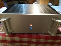
Spent 3 days making this amp. The words can not describe how good this amp sounds...
... lot No 1
lot No 2
Im curious what the snubber configuration that worked for codyt was, trying snubbers on my f6 did nothing.
Im curious what the snubber configuration that worked for codyt was, trying snubbers on my f6 did nothing.
I believe the values are Cx220nf/Cs100nf/Rs18r, but unable to verify until later this evening. *6L6* will know, as he helped me with it. Transformer is a Antek 4218 (worked well on a 3220 too). Using monolith bridge rectifiers 35A 200V.
Good news! After a month of waiting for some more LSJ74's to arrive in the UK Aleph J no2 is alive 😀
It is currently cooking slowly waiting for another check of bias and offset.
I think I damaged the JFETs with the zip tie when I pulled them together as the leg broke off one of them when I desoldered it..
Finally I will be able to listen to them!
It is currently cooking slowly waiting for another check of bias and offset.
I think I damaged the JFETs with the zip tie when I pulled them together as the leg broke off one of them when I desoldered it..
Finally I will be able to listen to them!
Attachments
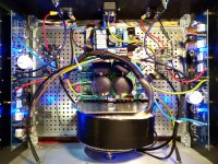
Good news! After a month of waiting for some more LSJ74's to arrive in the UK Aleph J no2 is alive 😀
It is currently cooking slowly waiting for another check of bias and offset.
I think I damaged the JFETs with the zip tie when I pulled them together as the leg broke off one of them when I desoldered it..
Finally I will be able to listen to them!
Congratulations, nice build! Which speaker protection boards did you use?
- Home
- Amplifiers
- Pass Labs
- Aleph J illustrated build guide