Hi Bambinz,
I suspect that you may have set Ang = 0.5 x Pi (eighth space). If so, change it to Ang = 2.0 x Pi (half space).
Hornresp calculates the response assuming a constant input voltage Eg. The input power varies depending upon the frequency-dependent impedance of the loudspeaker.
The diaphragm displacement is calculated assuming a constant input voltage Eg.
Kind regards,
David
I obtain an SPL higher than about 10dB respect the speaker sensitivity.
I suspect that you may have set Ang = 0.5 x Pi (eighth space). If so, change it to Ang = 2.0 x Pi (half space).
I think that maybe Hornesp use more than 1W to plot the graph.
Hornresp calculates the response assuming a constant input voltage Eg. The input power varies depending upon the frequency-dependent impedance of the loudspeaker.
Is the diagrahm of displacement calculated at the maximum power?
The diaphragm displacement is calculated assuming a constant input voltage Eg.
Kind regards,
David
Hi David,
Thank you very much!
I have set Ang = 1 x Pi, I have changed in 2 x Pi and the differences is lower. Now, is about 88dB instead of 86dB of the driver sensitivity. More realistic 🙂
A ok, therefore with an Eg of 2.83V and a 8 Ohm driver the response/displacement/ecc is calculated at 1W.
Another question, because when I use "calculate" the filling is not taken in account?
Thank you again for your help!
Hi Bambinz,
The input power will be 1W only when the frequency-dependent impedance of the loudspeaker (not the nominal impedance of the driver) is 8 ohms.
Correct. The effects of the absorbent filling material are only shown when the loudspeaker wizard is used.
Kind regards,
David
therefore with an Eg of 2.83V and a 8 Ohm driver the response/displacement/ecc is calculated at 1W.
The input power will be 1W only when the frequency-dependent impedance of the loudspeaker (not the nominal impedance of the driver) is 8 ohms.
Another question, because when I use "calculate" the filling is not taken in account?
Correct. The effects of the absorbent filling material are only shown when the loudspeaker wizard is used.
Kind regards,
David
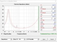
A OK! Therefore to know the power I should use the Eg voltage and the impedance graph
Perfect!
Thank you!!! ^^
Have a nice day 🙂
Perfect!
Thank you!!! ^^
Have a nice day 🙂
Correct. The effects of the absorbent filling material are only shown when the loudspeaker wizard is used.
I did not know that.
 Thanks for pointing it out. I had assumed everything on the 'input parameters' window would be used in the calculations.
Another stupid question:
The area of the mouth is the cross sectional area (plane surface), right? How is Hornresp handling curved wavefronts? Should we visualise/ conceptualise/ our design according to the surface area of the curved wavefront at the mouth, then find out the cross sectional area at that mouth and enter that into Hornresp? 😕
Therefore to know the power I should use the Eg voltage and the impedance graph
Hi Bambinz,
It's even easier than that - Hornresp will do it for you 🙂.
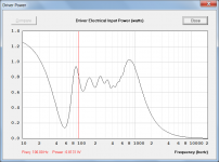
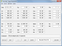
From the Acoustical Power chart window simply select menu Tools > Driver Power. Attachment 1 refers.
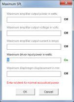
If for some reason you want to specify a constant power input rather than a constant voltage input, then the Maximum SPL tool should be used. Attachment 2 shows the setting required for a constant 1W input at all frequencies.
Kind regards,
David
Attachments
Hi SamAnytime,
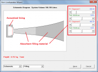
You assumed correctly, everything on the Input Parameters window is used. However the absorbent filling material parameters are not included on that window - they can only be accessed from the Loudspeaker Wizard, as shown in the attachment. (Fr and Tal on the Input Parameters window specify acoustical lining, not absorbent filling material).
No, you simply enter the plane surface cross-sectional area. Hornresp automatically calculates the curved wavefronts as necessary, based on the specified axisymmetric horn geometry.
Kind regards,
David
I had assumed everything on the 'input parameters' window would be used in the calculations.
You assumed correctly, everything on the Input Parameters window is used. However the absorbent filling material parameters are not included on that window - they can only be accessed from the Loudspeaker Wizard, as shown in the attachment. (Fr and Tal on the Input Parameters window specify acoustical lining, not absorbent filling material).
Should we visualise/ conceptualise/ our design according to the surface area of the curved wavefront at the mouth, then find out the cross sectional area at that mouth and enter that into Hornresp?
No, you simply enter the plane surface cross-sectional area. Hornresp automatically calculates the curved wavefronts as necessary, based on the specified axisymmetric horn geometry.
Kind regards,
David
Attachments
Thank you very much for the Help David!
And thank you for your software! I appreciate very much that you develope a free software for the comunity!
A question, is it possible to insert more than 4 segments? Because If I want simulate for example the Baby Labs of Woden Design I must insert 3 segment of different cross-section and in Hornesp is necessary to add a conical interface to put segment with different cross-section, therefor in necessary to add 3 segment + 2 conical interface = 5 segment.
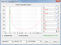
I had only half-fixed the problem. The fundamental resonance frequency for the test design is actually 81.9 Hz for both 46.8 and 46.9.
Thanks for the fix, David.
The extremely narrow throat is based on my half-ignorant presumption that the circumference of the throat is the lowest wavelength a conical horn can control directivity of.
Thanks Giri.
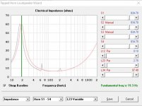
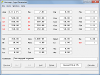
I have found the problem, and it will be fixed in the next update. The fundamental resonance frequency for your test design should actually be 249.8 Hz for both 46.8 and 46.9, as shown in the attachments.
Many thanks for reporting this issue. Even though it only occurs in extreme cases (the horn throat in your design is less than 4.7mm in diameter) the problem still needs fixing - I doubt that I would have ever found it myself 🙂.
Kind regards,
David
Hello David,
I found similar behavior in reported resonance value within 1mm of column length in a tapped horn simulation. I am using the updated version. Hope this helps.
Regards,
Giri
Attachments

Last edited:
is it possible to insert more than 4 segments? Because If I want simulate for example the Baby Labs of Woden Design I must insert 3 segment of different cross-section and in Hornesp is necessary to add a conical interface to put segment with different cross-section, therefor in necessary to add 3 segment + 2 conical interface = 5 segment.
Hi Bambinz,
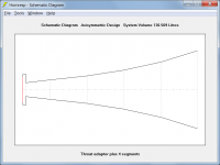
It is possible to get in effect five segments, by also including a throat adaptor as shown in Attachments 1 and 2.
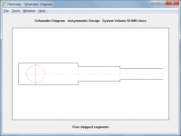
For the Baby Labs design though, I would probably use the offset driver (OD) option and specify stepped segments, as shown in Attachments 3 and 4.
(To specify stepped segments, double-click on any one of the S1 to S5 labels in edit mode - the labels will change colour from black to red).
Kind regards,
David
Attachments
Hi Giri,
Thanks for this second test example, it helps me to check that the proposed fix works with all loudspeaker types. The correct results for your TH design are as shown in the attachments.
The "next update" has not been released yet, which is why you are still getting the strange results.
Kind regards,
David
I found similar behavior in reported resonance value within 1mm of column length in a tapped horn simulation.
Thanks for this second test example, it helps me to check that the proposed fix works with all loudspeaker types. The correct results for your TH design are as shown in the attachments.
I am using the updated version.
The "next update" has not been released yet, which is why you are still getting the strange results.
Kind regards,
David
Attachments

Hi Bambinz,
It is possible to get in effect five segments, by also including a throat adaptor as shown in Attachments 1 and 2.
Kind regards,
David
Is that feature available for TH's? I'm sending from my phone.
Is that feature available for TH's? I'm sending from my phone.
Only if you are incredibly sneaky.
From what I've been able to figure out:
1. for multiple segment horns you are limited to exponential, conical, and parabolic. (no OSW, tractrix, etc.). Is this a plane/curved wavefront compatibility issue?
2. for the throat 'segment' you are limited to conical only.
1. for multiple segment horns you are limited to exponential, conical, and parabolic. (no OSW, tractrix, etc.). Is this a plane/curved wavefront compatibility issue?
2. for the throat 'segment' you are limited to conical only.
Only if you are incredibly sneaky.
Please tell us more, O Sneaky One... 🙂.
1. for multiple segment horns you are limited to exponential, conical, and parabolic. (no OSW, tractrix, etc.).
Correct.
Is this a plane/curved wavefront compatibility issue?.
No, it's just the way that Hornresp has evolved. It would be too difficult to change things now. A throat adaptor can be included though.
2. for the throat 'segment' you are limited to conical only.
If you mean the throat adaptor, then it can be conical, cylindrical, exponential or parabolic.
(Double-click the Lp label in edit mode or press C, E or P when the Lp text box has the focus).
Is that feature available for TH's?
In the case of a tapped horn a throat chamber port can be specified, but it is not a fifth segment.
Keeping asking again and again to David until he become so used to the idea that he've found all the keys in his mind to implement it without too much headache.Please tell us more, O Sneaky One... 🙂.
And finally again ask for christmas

- Home
- Loudspeakers
- Subwoofers
- Hornresp