PPS … that formula, I should have stated the 'standard form'
⋅-⋅-⋅ Just saying, ⋅-⋅-⋅
⋅-=≡ GoatGuy ✓ ≡=-⋅
Z = 1/(2πFC)
whereZ = impedance, in Ohms
F = frequency, in Hertz
C = capacitance, in Farads
π = pi, 3.14159265 … rounded to 3.14 for most calculations
And if you remember some of your high-school algebra, the equation can be “rearranged” quite nicely to find ANY of the terms, given all the others:F = frequency, in Hertz
C = capacitance, in Farads
π = pi, 3.14159265 … rounded to 3.14 for most calculations
Z = 1/(2πFC) … normal
C = 1/(2πFZ) … which I used above
F = 1/(2πZC) … which is helpful finding 'corner' frequencies
and in the case of the capacitor formulaC = 1/(2πFZ) … which I used above
F = 1/(2πZC) … which is helpful finding 'corner' frequencies
C … µF = 1,000,000 × F … so
C = 1/(2πFZ) … in farads is
C = 1,000,000 / (2πFZ) … in microfarads µF, and further dividing
1,000,000 ÷ 2π = 159,154 … is a useful constant to substitute in
C = 159,154 / FZ
might be worth remembering on its own, tho “old timers” just rememberC = 1/(2πFZ) … in farads is
C = 1,000,000 / (2πFZ) … in microfarads µF, and further dividing
1,000,000 ÷ 2π = 159,154 … is a useful constant to substitute in
C = 159,154 / FZ
C = 160,000 / FZ ... and again rearranged to
F = 160,000 / CZ ... with C in µF, and
Z = 160,000 / CF ... with C in uF, F in Hz
as it is plenty-accurate in 99.9% of the situations you might decide to use it. One of my very oldest and most respected friends actually preferred the 'kohm, uF' form for audio:F = 160,000 / CZ ... with C in µF, and
Z = 160,000 / CF ... with C in uF, F in Hz
C = 160 / FZ ... C=µF, Z=kohm, F=Hz, and rearranging to
F = 160 / CZ ... with C=µF, Z=kohm, F=Hz and
Z = 160 / CF ... with C=uF, Z=kohm, F=Hz
F = 160 / CZ ... with C=µF, Z=kohm, F=Hz and
Z = 160 / CF ... with C=uF, Z=kohm, F=Hz
⋅-⋅-⋅ Just saying, ⋅-⋅-⋅
⋅-=≡ GoatGuy ✓ ≡=-⋅
Last edited:
Capacitive impedance doesn't exist. Exists capacitive reactance. Impedance is a vector sum of resistance and reactance.
Its a duck...
Technically you are correct.
Practically, reactance and resistance are both measured in Ω.
So, just as technically if it walks like a duck, quacks like a duck, and smells like a duck, … its a duck.
Impedance = Ω
Resistance = Ω
Reactance = Ω
Its a duck.
⋅-=≡ GoatGuy ✓ ≡=-⋅
Capacitive impedance doesn't exist. Exists capacitive reactance. Impedance is a vector sum of resistance and reactance.
Technically you are correct.
Practically, reactance and resistance are both measured in Ω.
So, just as technically if it walks like a duck, quacks like a duck, and smells like a duck, … its a duck.
Impedance = Ω
Resistance = Ω
Reactance = Ω
Its a duck.
⋅-=≡ GoatGuy ✓ ≡=-⋅

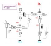
A problem might arrive when driving a solid state power amp with this 10 K output impedance. If the SS has 10 K input impedance, the poor 6SN7 would have to battle a 5 K load, which it wouldn't cope. Here's my take on the same subject (gain = 1).
Yah.
Except … maybe we've forgotten the word “preamplifier”, you know?
Taking in ±2 VRMS more-or-less at the max to the first triode. (especially with the input attenuator in your schematic) and using a choice of double-anode resistors to drop gain to an overall 1.0× (0 dB). Meaning the output will also flip along at ±2 VRMS. MAYBE ±10 V peaks! That'd be something.
So, driving the output (cathode) at +111 V is a little rich. Moreover, (and I'll grant it has the advantage of nice-glowing-valves), kind of an expensive voltage-follower function. Could just as easily use a sharp-cutoff MOSFET as a source-follower, with an unusual-but-it-works power resistor in the drain to drop B+ to maybe 100 V (and with no small irony, capacitor-bypassing it to ground!), then mmm… a similar arrangement of source resistors to achieve a 50 mA running current. ¹⁄₁₆ the cost. More linear. Unfortunately, no glowing tube.
Indeed, thought of that way, ONE single 6SN7 covers both left-and-right channels, and a pair of DN2540's to get the job done, at a buck apiece!
⋅-⋅-⋅ Just saying, ⋅-⋅-⋅
⋅-=≡ GoatGuy ✓ ≡=-⋅
3992R was the actual resistance (not impedance, as I didn't measure its inductance and capacitance 🙂 ). Just anticipating the next questions, where to put the control and how to lower gain...
JAAP?
Journal of American Acoustic Professionals? Couldn't quite figure it out.
Japan Acoustic and Audio Professionals?
Jamaican Alphorn Aerophone Pundits?
Yarrr… the boggled mind spins.
⋅-=≡ GoatGuy ✓ ≡=-⋅
Journal of American Acoustic Professionals? Couldn't quite figure it out.
Japan Acoustic and Audio Professionals?
Jamaican Alphorn Aerophone Pundits?
Yarrr… the boggled mind spins.
⋅-=≡ GoatGuy ✓ ≡=-⋅
It's simply my given name Goat, possibly shared by one of your ancestors if they are of Dutch origin 😉
Cloning, Etc
Interesting Ling, glad your memory is excellent. That last photo sure looks like that posted by rythmsandi. Is that a kit he might build? Looks very complete as is.
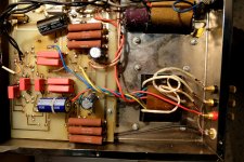
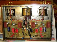
I was contacted a few years ago by someone in Europe who had bought a copy of something I'd published around yr 2000. The amp almost caught fire, the builder in Bankok, Thailand tried to go cheap on cathode resistors. With 50W under the chassis things got very hot. Don’t recall now what the failure was. Somehow the owner tracked me down thru a copy of the article published in Electronics World. I think the owner ended up scrapping the amp & building something else.
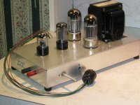
The amp is/was a boot strapped output section using two 6AS7s or 6080s per channel driven by a 2-stage diff amp, 6SL7 & 6SN7. About 25W audio per channel. I built a prototype only as a proof of concept. An article covering the amp was published in the May 1999 Issue of Glass Audio. And a shorter vers in the July 1998 Issue of Electronics World/UK.
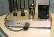
I’ve replaced the cathode WW resisters with heat sinking types mtd right against the aluminum chassis sides, but really needs external heat sinks. Not my daily driver, it sits on the shelf with many other brain storms.
Looks like there is money in clones, the copier has a nice looking BMW waiting at his front door. And I guess being copied is a compliment.🙂
Interesting Ling, glad your memory is excellent. That last photo sure looks like that posted by rythmsandi. Is that a kit he might build? Looks very complete as is.
I was contacted a few years ago by someone in Europe who had bought a copy of something I'd published around yr 2000. The amp almost caught fire, the builder in Bankok, Thailand tried to go cheap on cathode resistors. With 50W under the chassis things got very hot. Don’t recall now what the failure was. Somehow the owner tracked me down thru a copy of the article published in Electronics World. I think the owner ended up scrapping the amp & building something else.
The amp is/was a boot strapped output section using two 6AS7s or 6080s per channel driven by a 2-stage diff amp, 6SL7 & 6SN7. About 25W audio per channel. I built a prototype only as a proof of concept. An article covering the amp was published in the May 1999 Issue of Glass Audio. And a shorter vers in the July 1998 Issue of Electronics World/UK.
I’ve replaced the cathode WW resisters with heat sinking types mtd right against the aluminum chassis sides, but really needs external heat sinks. Not my daily driver, it sits on the shelf with many other brain storms.
Looks like there is money in clones, the copier has a nice looking BMW waiting at his front door. And I guess being copied is a compliment.🙂
Attachments
-
 DSCF1791 PC Board Failure 10C 20W.jpg272 KB · Views: 153
 -
 IMG_2973 Clone Amp 10C 16W.jpg230.6 KB · Views: 148
 -
 IMG_2982 10C 16W.jpg258.8 KB · Views: 142
 -
 IMG_3000 11W 20C.jpg110.8 KB · Views: 137
 -
 IMG_3002 BMW at Store Front 30C 16W.jpg221.5 KB · Views: 79
 -
 IMG_0476 A Different Kind Of Triode Amp 150 dpi.jpg350.3 KB · Views: 107
 -
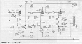 GA2_99 Fig 1.jpg91.6 KB · Views: 133
 -
 A Different Kind of Triode Amplifier Z.jpg77.2 KB · Views: 134
Probably my mind works that way. Do some complex stuff but at times I get few silly doubts😀rhythmsandy … the secondary pictures further support Fahey's contention, you know. While those are some solid specifications, in the end, your 6SN7 'preamp' with cathode-follower schematic has a lot of mmm… pointless… things going on.
Template-or-not, its kind of like taking pictures of a well-decorated wedding cake, and then asking questions about how much sugar to add to the eggs before making the batter.
As we say in America, “the curtains don't match the carpet”.
⋅-⋅-⋅ Just saying, ⋅-⋅-⋅
⋅-=≡ GoatGuy ✓ ≡=-⋅
Dropbox - amp chassis.PNG - Simplify your life
Dropbox - suamp.PNG - Simplify your life
Dropbox - suamp_in.PNG - Simplify your life
another build right from chassis design to complete assembly. Same spec as above 700WRMS into 2 channel subwoofer amp.
Dropbox - suamp.PNG - Simplify your life
Dropbox - suamp_in.PNG - Simplify your life
another build right from chassis design to complete assembly. Same spec as above 700WRMS into 2 channel subwoofer amp.
I had a discussion with one of the Audionote guy and he said they wouldn't use such output transformers instead of capacitors if it doesn't sound good. There are some preamp output transformers as expensive as 5000GBP made from 55 permalloy.
Secondly, I'm thinking why not use a 5:1 transformer at the anode of the second triode. Or if the circuit to be modified please tell me any changes to be done to accommodate the transformer.
in some of my builds, I have used Duelunds, Jensen and Mundorf PSU capacitors extensively. I don't want to spend that much in here but wanted to try the transformer though.
please look at the spec J&K Audio Design: Balanced Preamp Output Transformer
but that transformer is supposed to be used with Rp < 2k but with 6sn7 Rp is about 6700. So any modification to be done for that transformer spec that will be nice. Like said with 5:1 even if bypass cap is used the output gain will go close to 15 so with 5: 1 the preamp gain will be ample and moreover the noise performance will also be increased. No need to use active devices to convert from unbalanced to balanced hence I'm looking towards the transformer way.
Last edited:
Dropbox - amp chassis.PNG - Simplify your life
Dropbox - suamp.PNG - Simplify your life
Dropbox - suamp_in.PNG - Simplify your life
another build right from chassis design to complete assembly. Same spec as above 700WRMS into 2 channel subwoofer amp.
Do you work on the factory floor assembling this equipment?
Post a schematic & prove you know what you are talking about by describing the electronic part of its operation. Not interested at all about how it sounds. I'd like to discover if you know your stuff.🙂
Sofar I'm not convinced at all.
Do you work on the factory floor assembling this equipment?
Post a schematic & prove you know what you are talking about by describing the electronic part of its operation. Not interested at all about how it sounds. I'd like to discover if you know your stuff.🙂
Sofar I'm not convinced at all.
I'm not authorized to post the schematic anywhere or else I could have shared. On the front its double differential input, simple EF VAs and triple EF output stage. All bipolar stages. Regulated front end. Mains with CM chokes and DC filters with inrush current limiting. Microcontroller is in progress for all the checking of tunon and off and protection modes.
why not look at just one triode and use trafo on the anode like below:
https://ia800105.us.archive.org/29/items/Tango_NP-216N/Tango_NP-216N.pdf
http://1.bp.blogspot.com/-3mq_YJ2xJPM/T98YeV7e7hI/AAAAAAAAB-s/9iMDA0k3fbs/s1600/JELsc-TClinepre.jpg
https://ia800105.us.archive.org/29/items/Tango_NP-216N/Tango_NP-216N.pdf
http://1.bp.blogspot.com/-3mq_YJ2xJPM/T98YeV7e7hI/AAAAAAAAB-s/9iMDA0k3fbs/s1600/JELsc-TClinepre.jpg
Seriously…
DO WHATEVER you like.
At some point you “drank the Koolaid”, and became convinced expensive caps…
… was the best way to achieve legendary sound quality.
Now you are entranced with using a transformer instead.
… because it is ostensibly “sweeter” and either somewhat-less or somewhat similar cost.
As I said… DO IT.
No need to discuss.
Buy a couple of transformers, a couple of 6SN7's, and breadboard the project.
Buy a small spool of fine gauge braid-shielded coax, so your project isn't too noisy.
Ought to be able to do something like this — with a normal assortment of parts — in perhaps 2 evenings.
Sigh…
⋅-⋅-⋅ Just saying, ⋅-⋅-⋅
⋅-=≡ GoatGuy ✓ ≡=-⋅
So it is not your design. You are employed to assemble the parts. I'm really impressed now. Just build something, stop talking about what you might do.I'm not authorized to post the schematic anywhere or else I could have shared. On the front its double differential input, simple EF VAs and triple EF output stage. All bipolar stages. Regulated front end. Mains with CM chokes and DC filters with inrush current limiting. Microcontroller is in progress for all the checking of tunon and off and protection modes.
Talk is cheap.😀
I probably shouldn't butt in here; but here goes. I personally prefer the sound of transformer coupled output to capacitor coupled output. But to achieve this takes a really good line out transformer and they aren't cheap. It also requires designing the circuit for transformer output. It's not something that can be necessarily grafted onto some existing design.
Second, a 6SN7 has too high a plate impedance to drive a transformer effectively. That would require a very high primary inductance for decent bass response but that in turn would require more windings. That results in more winding capacitance which interacts with the plate resistance to kill the high frequency response. You're going to have to use a higher transconductance tube and more B+ current to bias that tube. So PS is going to have to be able to handle the extra load.
I'm currently in the process of building a headphone amp with a modified 6SN7 mu follower (Morgan Jones "beta follower") doing input/voltage gain duty. In Jones' circuit the load resistor is replaced by an PNP transistor. This has three advantages: 1) consumes less B+, 2) output of the lower tube is direct coupled to the upper - no capacitor and 3) the AC impedance of the upper tube is multiplied by the transconductance of the transistor ( hence beta follower). This presents the lower tube's plate with a much higher impedance load. The output is RC coupled to the following stage, a transformer loaded 6BX7. With a plate resistance of ~2.5K the rule of four would suggest a primary impedance of 10K. If interested I will let you know if it sounds any good when I'm finished.
Good luck with your project.
Interest is always there John, please do show your results.
Popular thought (at this moment in time) is that if the load impedance is high enough, it's not doing any sonic harm. The not cypher convinced builders argue the sonic character is noticable with each active load. For me it's virgin ground, reason to build the circuit I came up with.
Popular thought (at this moment in time) is that if the load impedance is high enough, it's not doing any sonic harm. The not cypher convinced builders argue the sonic character is noticable with each active load. For me it's virgin ground, reason to build the circuit I came up with.
- Home
- Amplifiers
- Tubes / Valves
- output transformer spec for 6SN7 Cathode Follower