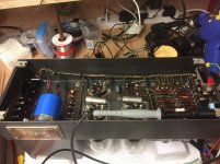
An old Luxman L-210. Two previous jobs, both done poorly. One channel had shorted outputs and the heat sink was a mess of smeared compound. The shorted channel got the proper type of new output transistors and also driver transistors. The bias transistor measured fine and close to the other channel. I had to take the heat sink out and clean the mess off it. What a mess it was. The channel that didn't blow had improper output transistors, not even a complimentary pair! Since that came in working, the driver transistors were left in place. All outputs got new mica insulators. Evidence showed that in both previous jobs, no new thermal compound was applied to the transistors, or if it was, it was not nearly enough. Replaced the fuse and brought it up on a variac slowly watching both bias current levels. It came up without any theatrics with very low DC offsets. The bias currents were corrected, then it passed all tests. Nice for a change, no hidden faults.
-Chris
-Chris
Hi Chris,
I just love those "prior repairs" jobs - it allows me to use words not heard in church.
Slobs, some of these people are.
But, alas, the world is made up of many types, right?
I just love those "prior repairs" jobs - it allows me to use words not heard in church.
Slobs, some of these people are.
But, alas, the world is made up of many types, right?
Well, yes. One of them lost all the original screws for both the top and bottom covers. All I can really do is ask why? Is it so hard to store the screws together?
-Chris
-Chris
Very disappointed.
Built up two dual channel PC USB oscilloscopes.
They are through hole expcept for A2D and PIC microcontroller.
Neither worked on first power up and only one PIC would program.
So it had to be SMD not soldered right.
Re-soldered the 1mm pitch PIC and managed to get it to program.
The A2D are 0.5mm pitch and real pigs to solder without getting shorts.
So I put in a row of via's down the side of the SMD chips so I can buzz for shorts.
I re-soldered the A2D and managed to get them working.
Not really sure what's going on with bad soldering. All my through hole joints are fine.
I run up and down the pins two or three times to ensure soldered but some just don't solder. Maybe a touch of oxidisation ? I use flux before soldering but doesn't seem to make any difference.
I need to use SMD to get fast A2D and microcontroller.
Its a bit of a worry with SMD but after getting them working I twist the pcb a bit to make sure there are no bad joints.
Well, yes. One of them lost all the original screws for both the top and bottom covers. All I can really do is ask why? Is it so hard to store the screws together?
-Chris
Indeed.
I keep a sectioned tray on the bench for screws that I remove.
It's actually a 6 section change tray taken from a drawer of a cash register.
Also, those senior citizen multiple pill containers are a good idea to have around.
Sometimes, I feel like I'm the only one around with some common sense.
I have dis-assembled bundles of HP and Tek test equipment -- and retain as much of the hardware as possible. My wife plans to bury me with it.
I have dis-assembled bundles of HP and Tek test equipment -- and retain as much of the hardware as possible. My wife plans to bury me with it.
Yeah, I've always "saved" screws and related stuff when tearing down something for junk.
I got jars of screws, nuts, bolts!
Also, those senior citizen multiple pill containers are a good idea to have around.
Being a "senile citizen" myself, my insurance company keeps sending me these things. They are quite useful for keeping all those little SMD thingies sorted.
Is it so hard to store the screws together?
In post #582 I showed a picture of a laptop in a totally disassembled state since I had to swap the keyboard, which was likely the first part installed during manufacture. Note the two Walmart prescription pill bottles. One is for all the screws from the outside of the laptop, and the other all the screws and small parts from the inside. More complicated surgeries get more bottles / boxes.
My first rebuild of an automatic transmission in 1975 used several boxes, bags and cafeteria trays each with labels and associated Polaroid pictures for reassembly. The operation was successful. Today I set one or two digital cameras on tripods each taking one picture per second so my "senile citizen" brain can put things back together.
dis-assembled bundles of HP and Tek test equipment -- and retain as much of the hardware as possible.
Some old HP stuff used stainless hardware. I have several pounds of it.
I got jars of screws, nuts, bolts!
The jars became boxes, which became totes. Someday I'm going to sort it all......yeah, right!
Not really sure what's going on with bad soldering. All my through hole joints are fine.
I learned years ago to coat the PCB and device to be soldered with flux, solder a long blob down each row of pins not worrying about the solder shorts. Then go back with a microscope and solder wick and remove the excess solder and fix the shorts. Avoid QFN (quad flat no-lead) packages whenever possible since these are the biggest pain to hand solder.
Today I use the frying pan method (named after my first attempt). I use a syringe to put solder paste on each pad. Then place the parts on the pads in the solder. Place the entire PCB on a hot plate set to about 270C until all the solder reflows, then carefully transfer the hot board on to a heat sink for cooling. The use the microscope to fix the issues.
I use one of these now, but I used to use a magnetic bowl...
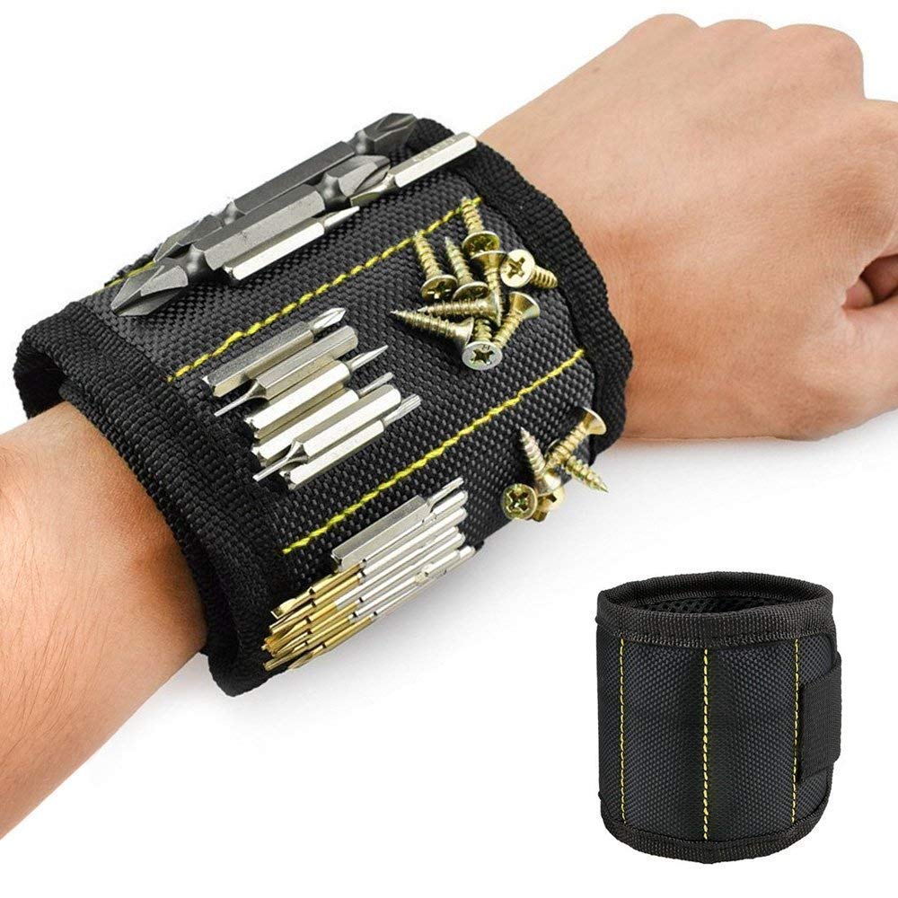
https://www.amazon.ca/gp/product/B07KH4NVPG/ref=ppx_yo_dt_b_asin_title_o05_s01?ie=UTF8&psc=1
https://www.amazon.ca/gp/product/B07KH4NVPG/ref=ppx_yo_dt_b_asin_title_o05_s01?ie=UTF8&psc=1
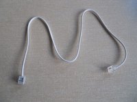
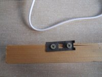
Not strictly a repair but I wanted to shorten a router cable that used RJ11 plugs... and never having attempted such a thing and not wanting to fork out for a crimping tool...
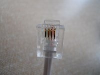
I think it turned out pretty well tbh using a thin bit of metal as a press. A piece of paper between the metal and the gold pins protected them from getting marked.
I think it turned out pretty well tbh using a thin bit of metal as a press. A piece of paper between the metal and the gold pins protected them from getting marked.
Attachments
Hi Karl,
Cool! I have the proper tools for this, so I winced when you said you did it without the crimper. Did you know that they are two types of plugs? One for solid wire, and one for stranded cable.
As for hardware, I use labeled pill bottles, and I do have a "hell box" full of various screws.
-Chris
Cool! I have the proper tools for this, so I winced when you said you did it without the crimper. Did you know that they are two types of plugs? One for solid wire, and one for stranded cable.
As for hardware, I use labeled pill bottles, and I do have a "hell box" full of various screws.
-Chris
Erm... nope, I didn't know that 🙂
So I'm looking up what I actually used and the only bit of info I can find is from a generic search of the manufacturer part number.
The data sheet makes no mention of solid/stranded that I can see.
https://cpc.farnell.com/mh-connecto...&ddkey=https:en-CPC/CPC_United_Kingdom/search
So I'm looking up what I actually used and the only bit of info I can find is from a generic search of the manufacturer part number.
The data sheet makes no mention of solid/stranded that I can see.
https://cpc.farnell.com/mh-connecto...&ddkey=https:en-CPC/CPC_United_Kingdom/search
Attachments

Hi Karl,
It looks like you have the right ones.
I carry both, but a lot more ends for solid wire. Those are used to make harnesses for the system end (or KSU). One end are these RJ-11 plugs and the other terminates on a BIX-1A block.
It looks like you have the right ones.
I carry both, but a lot more ends for solid wire. Those are used to make harnesses for the system end (or KSU). One end are these RJ-11 plugs and the other terminates on a BIX-1A block.
Thanks Chris. It's working just fine and looks a whole lot neater than the 2M or whatever lead that comes with the router.
Quad CD 66
The player had been dropped / damaged on one corner so the drawer would not open properly.
On taking the player apart, I found that the front panel had a twist.
This was straightened using (careful) brute force and a straight edge.
The power switch operating bar and knob had also taken a bash so was carefully straightened.
On reassembly, the drawer still did not open/shut correctly.
One of the drawer guides had broken in half so was not holding the drawer.
Luckily I had a spare CDM4 mechanism so substituting the guide pin solved the problem.
The player now works and sounds excellent!!
What to do with it now as I already own one
Andy
Hi Karl,
Not surprising, given how much those actually cost landed, and then what they cost each to make ... the connector you put on probably cost you more than that entire cable was charged out by the factory. Actually, there is no probably about it.
Hi poynton,
-Chris
Not surprising, given how much those actually cost landed, and then what they cost each to make ... the connector you put on probably cost you more than that entire cable was charged out by the factory. Actually, there is no probably about it.
Hi poynton,
Well, if you like your unit, then keep this as a spare. If not that, then put it in the bedroom with the rest of a stereo system (my wife loves ours) or with the computer or your DIY work bench. I have CD players in all those locations at home. If you were inspired, you could work to increase the sound quality of it. Once you come to a decision, you can repeat the same work to your other machine and end up with a pair of improved machines to listen to.What to do with it now as I already own one
-Chris
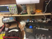
Finally got up the nerve to put my Quad IIs under power. They had come to me from a friend who had found them abandoned in a basement. One of the KT66s was smashed, and there were some dodgy homemade connection wires, so I considered them as being in an unknown state. Most of the resistors tested high, and one of the can caps was way out. So I did a full restore; nothing fancy except the Russian KY caps. Resistors are now 1% metal films. I’m planning on keeping these so I was mostly concerned with giving them a new lease on life.
Today I powered them both up on the variac and a dummy load. Pure sine wave goodness came through on the oscilloscope. So it looks like all the iron is in good shape. Haven’t yet put them on real speakers though.
Edit: Oh, and a new set of matched valves that I bought from the new Brimar folks. I know they’re just rebadged but I really like what they’re trying to do. Again, nothing exotic — just good quality stuff.
Attachments

Last edited:
Looks good with the Brimar valves installed. Neat job.
With modern resistors, you must check the voltage rating! Don't be surprised to see some rated at 100V. The old carbon composition resistors in a 1/2W were rated for 500 or 600 volts (I can't remember which). All I know is that when I rebuild tube equipment the voltage rating of the resistor is very important.
If you exceed the rating, they may not fail right away. They will arc inside and you may not even see this under the coating.
-Chris
Thanks for the reminder, Chris. I used TE/Holsworthy H4P 1 watt throughout which have a 500V rating, except for R4 where I used a Dale 1W CPF. This only has a 250V rating, but it sits on the cathodes of the EF86s where the schematic gives 2.2V. R12 is a Welwyn 7W W22 rated at 200V, but should only see 26V as far as I can tell.
https://drtube.com/schematics/quad/quad-ii.gif
https://drtube.com/schematics/quad/quad-ii.gif
Last edited:
Hi ahankinson,
Isn't it amazing how much you can remember, all those small details?
I normally use the higher power resistors in tube gear to get the longer body so the leads reach, that and the higher voltage ratings. I'm constantly making certain the resistors will stand up to even fault voltages (except in the cathode circuit where the current will burn them out in a failure).
Nice job overall.
-Chris
- Home
- Member Areas
- The Lounge
- What did you last repair?