Excellent idea Prasi
I like how compact it is without using SMT stuff.
Would you mind sharing the Gerber w us ? It’s been a while I haven’t order PCB.
Thanks and happy holidays
Eric
I like how compact it is without using SMT stuff.
Would you mind sharing the Gerber w us ? It’s been a while I haven’t order PCB.
Thanks and happy holidays
Eric
Hello Eric,
Thanks for the kind words. Thanks also for the wishes, wish the same to you all.
I am working on a compact practical layout that can work with crc/ just bulk cap psu's both for positive and negative voltages. I am getting some help from an Australian gentleman friend.
So , I will share gerbers alright, when we are happy the layout (both of us).
Regards
Prasi
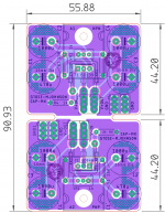
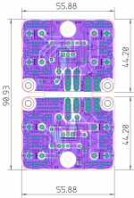
Here are the two options worked out, considering both positive and negative rails and output bulk cap on CMX PCB.
First one is what I prefer, though it making one to cross wires from input to output for negative rail and inconvenient grounding though.
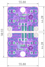
second one is a layout thats very convenient for conventional builds and uses human intuition for positive and negative rails. And is simply "build it" kind of layout.
regards
prasi
First one is what I prefer, though it making one to cross wires from input to output for negative rail and inconvenient grounding though.
second one is a layout thats very convenient for conventional builds and uses human intuition for positive and negative rails. And is simply "build it" kind of layout.
regards
prasi
Attachments

Very nice, I prefer the second layout simply because it’s more symmetrical...must be an EE thing...lol
Could you please add some mounting holes at some of the corners.
BR
Eric
Could you please add some mounting holes at some of the corners.
BR
Eric
Very nice, I prefer the second layout simply because it’s more symmetrical...must be an EE thing...lol
Could you please add some mounting holes at some of the corners.
BR
Eric
Yes its a nice layout, but I also think mounting holes are useful.
Thanks Prasi for another 'masterful' design - very neatly done.
There is readily available double sided tape in various thicknesses to support the board under the 'flat spots' - the power pass devices have 20mm long legs so mounting it won't be difficult and quite strong enough to support the board and caps - solid copper links to the main power supply board will help so mounting holes ...
the Cap-Mx GND connections go to the main power supply central GND point at the output terminals
Power/heat? If the Cap-Mx is set to drop around 2 volts on the big pass transistor and is supplying both channels of a class A amp at 1.5A (2v x 3A/rail) = approx. 12W for both rails, both channels (if my arithmetic is okay) so quite manageable.
A rather useful little device - thanks again Prasi.
The mounting holes would just be there to provide reinforcements near the spade terminals. I can see the pcb bending or breaking easily while inserting the crimp terminals.
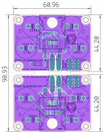
here is version with mounting holes. I had to increase the size by 5 mm.
probably we can do away with extreme corner mounting holes as there is the big power tranny (or some part of it) to support the PCB at the extreme outer edge.
If the 2 extreme mounting holes are removed, I can maintain earlier size and probably make it same as earlier design (pic no. 2 in my post above).
prasi
PS: I want to make this design as useful and convenient as possible so that most diyer's want to try it in their builds and see for themselves if its beneficial for them.
Attachments
Last edited:
Hi Prasi, is the mounting screw for the output transistor enough and the other four mounting holes are not required? It looks like the edges may short with the chassis if there is nothing in the corners, or am I being paranoid? The smaller size obviously has appeal. Either way I would like a couple🙂

Happy new year Prasi, I don't think those 4 outmost corner mounting holes are necessary, the BJT mounting holes should support that area nicely. Most people are worried about the lack of support near the spade connectors, especially with the cutout, the board can flex and will break with repetitive use.here is version with mounting holes. I had to increase the size by 5 mm.
probably we can do away with extreme corner mounting holes as there is the big power tranny (or some part of it) to support the PCB at the extreme outer edge.
If the 2 extreme mounting holes are removed, I can maintain earlier size and probably make it same as earlier design (pic no. 2 in my post above).
prasi
Thank you guys for the suggestions ...
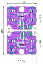
here is the modified version. extreme corner holes removed and size maintained.
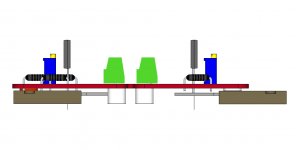
to-264 is about 5 mm thick. so one can use 5-7 mm stand offs for the inside mounting holes and for the other extreme edge , one can do one of the following...
1. Slide the TO-264 as far back as possible to use some existing mounting hole. let the extreme edge of pcb rest on some part of the TO-264. (use 5mm stand-off in this case)
2. use the TO-264 mounting hole to bolt pcb to bottom plate / heat sink. (use 7 mm stand-off for holes and 1-2 mm washer between bjt and pcb bottom).. We are soldering THT components , so we have to keep sufficient clearance between BJT top surface and bottom of pcb.
Hope its clear.....😀
I will try to make some 3d models and post here...
here is the modified version. extreme corner holes removed and size maintained.
to-264 is about 5 mm thick. so one can use 5-7 mm stand offs for the inside mounting holes and for the other extreme edge , one can do one of the following...
1. Slide the TO-264 as far back as possible to use some existing mounting hole. let the extreme edge of pcb rest on some part of the TO-264. (use 5mm stand-off in this case)
2. use the TO-264 mounting hole to bolt pcb to bottom plate / heat sink. (use 7 mm stand-off for holes and 1-2 mm washer between bjt and pcb bottom).. We are soldering THT components , so we have to keep sufficient clearance between BJT top surface and bottom of pcb.
Hope its clear.....😀
I will try to make some 3d models and post here...
Attachments
Last edited:
this one is the best I think. Whats a good pass transistor to use here? Does speed matter or just gain?
Last edited:
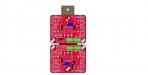
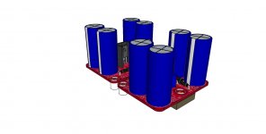
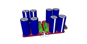
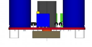
Here are some 3-D pics to given an idea of mounting as per the 2 options I had posted above..
Also posted are the gerbers, sch and stuffing guide..
Also posted are the gerbers, sch and stuffing guide..
Attachments
-
 top.jpg147.6 KB · Views: 619
 -
 side.jpg51.2 KB · Views: 992
 -
 iso2.jpg96 KB · Views: 979
 -
 iso.jpg122.5 KB · Views: 997
 -
 front.jpg68.6 KB · Views: 1,019
 -
 top2.jpg150.1 KB · Views: 480
 -
 cap mx 4.1.png105.5 KB · Views: 622
 -
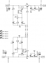 cap mx 4.1-sch.png10 KB · Views: 830
 -
gerbers-CRC PSU_LT4320_CMX-4.1_2020-01-04.zip395.2 KB · Views: 207
Last edited:
Whats a good pass transistor to use here? Does speed matter or just gain?
One could use highest gain devices , as gain is most important.
Hello Eric,
Yes, I have provided a separate gerber file containing 'v-score' layer in the middle in the attached gebers here.
Hello Luke,
I could do a GB if there is more interest (20-30 nos.), pcbs would be in 2.4mm thickness and 70um copper. So here is list
prasi-2 nos.
jameshillj-4 nos.
Luke-2 nos.
Otherwise I can order a batch of 10 pcbs from China and send you couple. Lets wait a day or two to see.
regards
Prasi
Attachments
Hi Prasi
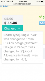
I received a quote from PCBway, instead of the regular $5 (up to 10 regular size 100mm x 100mm max.) I received the following $44 quote.
Seems that it’s more work for them.
BR
Eric
I received a quote from PCBway, instead of the regular $5 (up to 10 regular size 100mm x 100mm max.) I received the following $44 quote.
Seems that it’s more work for them.
BR
Eric
Attachments
Last edited:
You could try PCB Prototype & PCB Fabrication Manufacturer - JLCPCB and see if you get a lower quote.
- Home
- Amplifiers
- Power Supplies
- Juma's Easy-Peasy Capacitance Multiplier