You are too kind. Anyway, I continued to think about this problem of separating out the reflections. I beat my head against, in fact, until finally some sense penetrated.
I modeled a conical horn that I hoped was big enough that the mouth reflection would be far enough out in time to be separable.
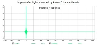
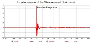
Then I tried to separate it with impulse gating. In playing with the gated impulse in REW calculator I inverted the impulse and got a flat line in frequency and phase.
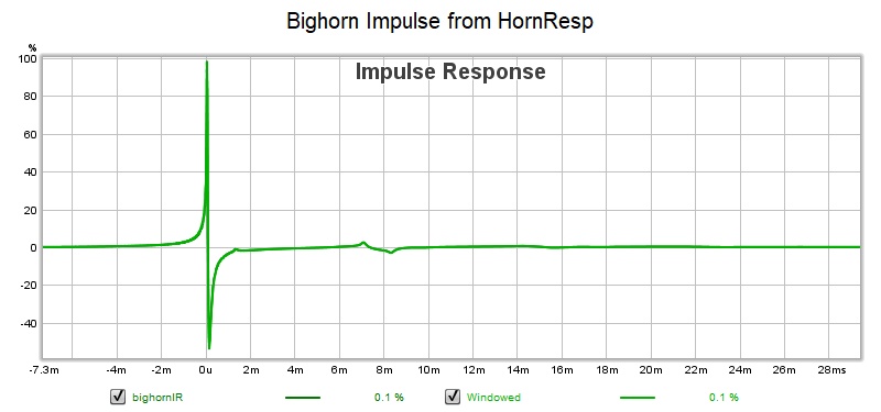
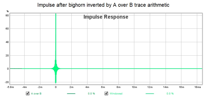
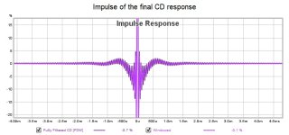
Not a perfect dirac because of the ringing but all traces of the reflections are gone! Simply by inverting the measurement impulse we not only cancelled the mouth reflections but we also equalized the response.
I modeled a conical horn that I hoped was big enough that the mouth reflection would be far enough out in time to be separable.
Then I tried to separate it with impulse gating. In playing with the gated impulse in REW calculator I inverted the impulse and got a flat line in frequency and phase.
Not a perfect dirac because of the ringing but all traces of the reflections are gone! Simply by inverting the measurement impulse we not only cancelled the mouth reflections but we also equalized the response.
Attachments
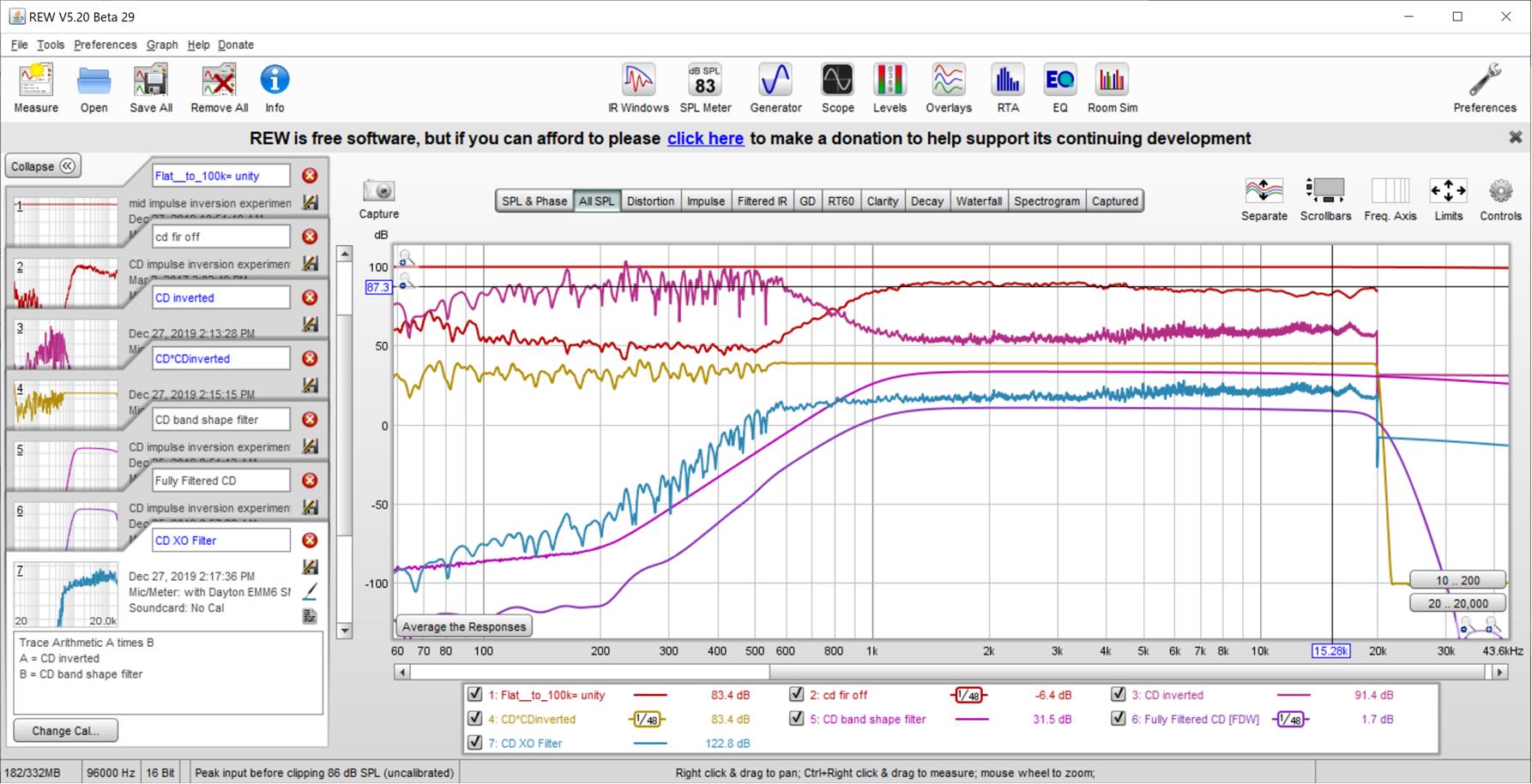
So what do we do with this insight - that inverting the impulse eliminates the reflections? We already knew that since some room equalization products do exactly that and are aware that its not necessarily the best thing to do, depending on where/how the measurement was taken and where the reflections are from. Reflections by definition are not minimum phase and as a general rule we don't equalize non-minimum phase artifacts. But the same math that equalizes by impulse response inversion also cancels reflections. And if the only reflections in the measurement are those from the mouth and throat of a constant directivity horn, the chances are good that the corrections will be of benefit over a wide enough area to be useful.
What I would encourage you to do Mark is to make another crossover for your Synergy in which the "equalize flat for a couple octaves around crossover" steps before applying the target XO slope filter is replaced by a "invert device measurement impulse" step. Use that inverted measurement impulse as a filter in the XO in place of the prior flattening filter, cascaded with the other XO filters.
Since the impulse inversion filter equalizes the measurement flat from DC to daylight it will need to be cascaded with a filter to respect device limitations. E.g. a woofer will need a high pass filter that restores its natural roll off, a tweeter will need a low pass.
Hopefully you will get a sweeter sweet spot out of this and not do perceptible damage to the response in the rest of the room.
Last edited:
I suspect that restoring natural roll off at both ends of the spectrum will take care of the impulse ringingSince the impulse inversion filter equalizes the measurement flat from DC to daylight it will need to be cascaded with a filter to respect device limitations. E.g. a woofer will need a high pass filter that restores its natural roll off, a tweeter will need a low pass.
Applied technique to my synergy mid simulations
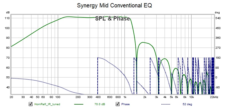
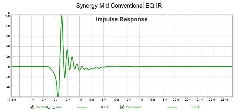
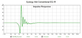
First the result with conventional EQ
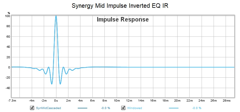
Now the results by impulse inversion EQ with second linear phase filter to set roll off at each end of band

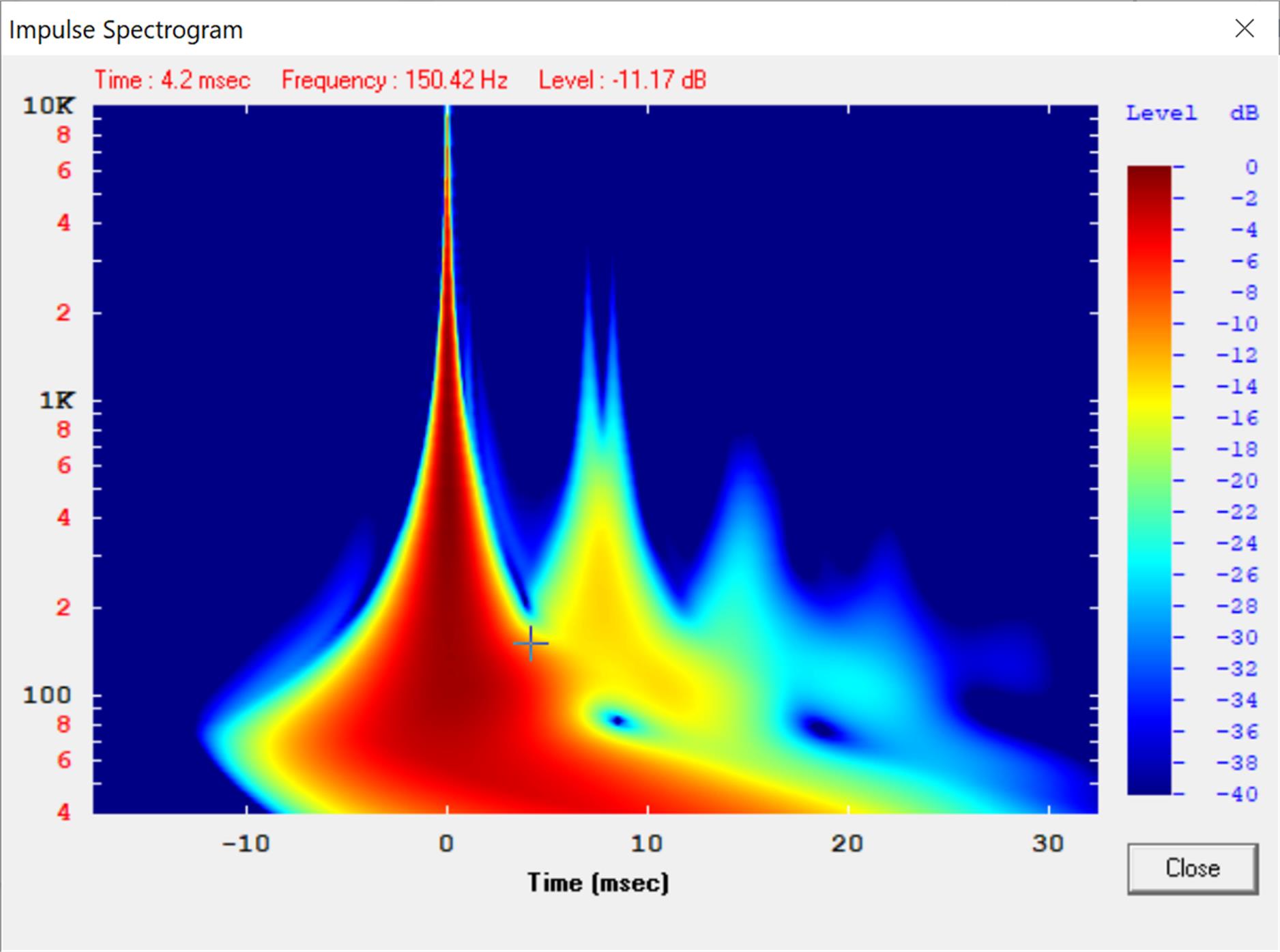
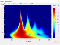
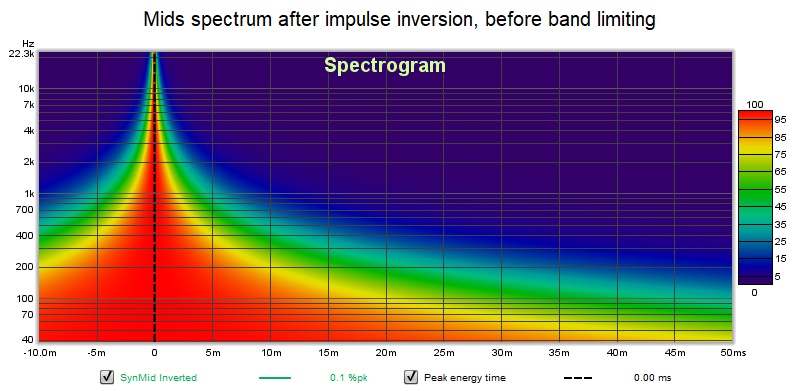
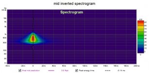
Looking at spectrograms shows I need to pay more attention to the filter that establishes the roll off at each end of the mids band 100 hz to 1 khz.
The spectrogram before bandlimiting is ideal
the spectrogram with bandlimiting departs from ideal outside the mid's passband
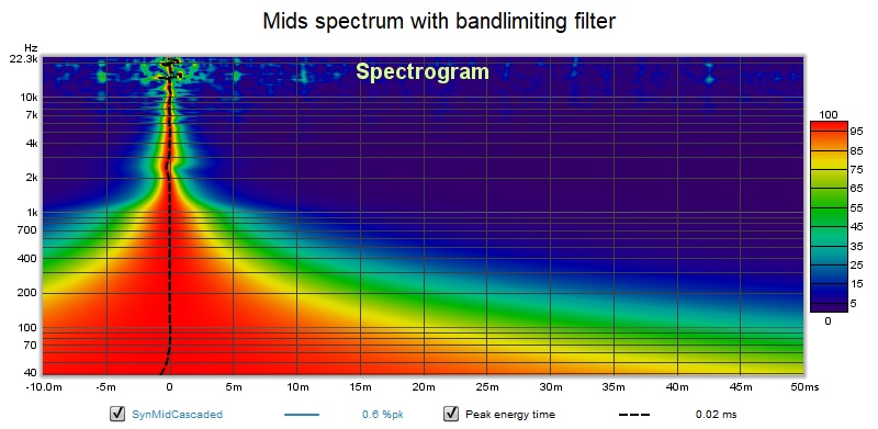
This confirms my suspicion that establishing smooth roll off at both ends of the band would reduce/eliminate the impulse ringing seen after impulse inversion
First the result with conventional EQ
Now the results by impulse inversion EQ with second linear phase filter to set roll off at each end of band
Looking at spectrograms shows I need to pay more attention to the filter that establishes the roll off at each end of the mids band 100 hz to 1 khz.
The spectrogram before bandlimiting is ideal
the spectrogram with bandlimiting departs from ideal outside the mid's passband
This confirms my suspicion that establishing smooth roll off at both ends of the band would reduce/eliminate the impulse ringing seen after impulse inversion
Attachments
-
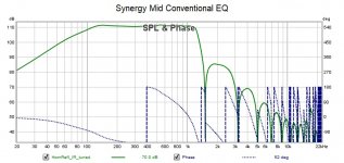 Synergy Mid Conventional EQ.jpg92.1 KB · Views: 220
 -
 Synergy Mid Conventional EQ IR.jpg63.7 KB · Views: 218
 -
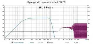 Synergy Mid Impulse Inverted EQ FR.jpg79 KB · Views: 217
 -
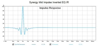 Synergy Mid Impulse Inverted EQ IR.jpg61.8 KB · Views: 217
 -
 Mids spectrum with bandlimiting filter.jpg107.6 KB · Views: 222
 -
 Mids spectrum after impulse inversion.jpg105.4 KB · Views: 217
To complete the comparison, here is the spectrogram of the raw, unEQed mid response
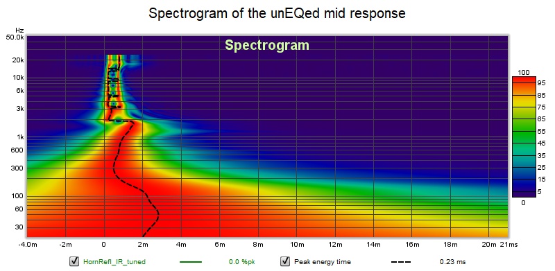
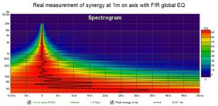
I actually built this design so I will dig down into my archives and see how it measured. This response has the IIR EQ and XO with a laver of FIR global EQ

I was able to flatten the phase. The room is intruding even with the mic at 1m from the corner horn. The mid reflection from the throat isn't apparent because its a system response with XO below the reflection null. Mouth reflections were 26 db or so down in the sim and aren't visible in the REW spectrograms.
I don't think I need to point out that these comparisons aren't quite apples to apples. They don't establish a dramatic improvement except perhaps in the shape of the IR, whereas FRs were substantially the same.
I think listening tests are needed to know if this is worth the effort. Don't forget the mouth reflections we wanted to eliminate were down 26 db to begin with.
I actually built this design so I will dig down into my archives and see how it measured. This response has the IIR EQ and XO with a laver of FIR global EQ
I was able to flatten the phase. The room is intruding even with the mic at 1m from the corner horn. The mid reflection from the throat isn't apparent because its a system response with XO below the reflection null. Mouth reflections were 26 db or so down in the sim and aren't visible in the REW spectrograms.
I don't think I need to point out that these comparisons aren't quite apples to apples. They don't establish a dramatic improvement except perhaps in the shape of the IR, whereas FRs were substantially the same.
I think listening tests are needed to know if this is worth the effort. Don't forget the mouth reflections we wanted to eliminate were down 26 db to begin with.
Attachments

So what do we do with this insight - that inverting the impulse eliminates the reflections? We already knew that since some room equalization products do exactly that and are aware that its not necessarily the best thing to do, depending on where/how the measurement was taken and where the reflections are from. Reflections by definition are not minimum phase and as a general rule we don't equalize non-minimum phase artifacts. But the same math that equalizes by impulse response inversion also cancels reflections. And if the only reflections in the measurement are those from the mouth and throat of a constant directivity horn, the chances are good that the corrections will be of benefit over a wide enough area to be useful.
What I would encourage you to do Mark is to make another crossover for your Synergy in which the "equalize flat for a couple octaves around crossover" steps before applying the target XO slope filter is replaced by a "invert device measurement impulse" step. Use that inverted measurement impulse as a filter in the XO in place of the prior flattening filter, cascaded with the other XO filters.
Since the impulse inversion filter equalizes the measurement flat from DC to daylight it will need to be cascaded with a filter to respect device limitations. E.g. a woofer will need a high pass filter that restores its natural roll off, a tweeter will need a low pass.
Hopefully you will get a sweeter sweet spot out of this and not do perceptible damage to the response in the rest of the room.
Great stuff.....
Yes, I see how impulse inversion can substitute for flattening stage I've been using pre crossover. I've always thought impulse inversion is basically what a FIR generator does. That flattening prior to the inversion/generation was for 'seeding' the impulse inversion, to kinda help assure the inversion results are sane. But that's just been intuition mainly....
When I was getting really strange results from letting the FirD generator handle all stages at once, flattening, crossover insertion, and target matching mag and phase, I went back to rephrase and starting spitting out stages and cascading the protective/rolloff/crossover filters as you describe. It helped me see the measurements from my synergy were more fickle than I was accustomed to, and measurement and correction needed to be approached much more carefully.
I like the elegance you propose of a simple impulse inversion as first stage.
It should do the same thing as flattening, but of course wider in freq as you say. I guess the major issue will be how much out of band validity do I have in the measurement.
I've also thought many times that a Fir file built from response at the mouth should theoretically correct the horn reflections too.
It's just the Dave G. patents read like he might be making the corrections in two ways...one for the mouth, and one for reflections returning to throat.
Maybe that's just a smoke screen, to hide what's really being done...??
Hard to tell when stuff is down 26 dB to begin with...huh?
Anyway, continuing big thanks...all makes sense ...I'll play with impulse inversion at beginning..
I believe the reflections must be measured from throat since measuring with mic at the mouth you'll get very different results depending where the mic is at. Fix for one mic position and the others get worse. If i remember mouth wasn't even mentioned in the Gunnes papers? Anyway, gotta return this at some point, my brain has been elsewhere for too long to remember details from the thread  It is great to see others are intriqued by the topic as well! Happy holidays!
It is great to see others are intriqued by the topic as well! Happy holidays!Had tmuikku not posted I would have observed that no doubt D. Gunness is smarter than me and knows more about this than I do. If I knew a way to separate out the phase plug effects from the horn effects I would. So following up that thought, perhaps measure with a mic in the throat or on a plane wave tube to correct for the phase plug reflections. Then put the CD on the horn and measure with the first correction filter in place and make a measurement at or past the mouth to derive a correction filter for the horn, including mouth reflections. No doubt there is some learning to be done about how and where to take these measurements and whether to use single point or multiple measurements.
These details are conspicuously absent from the Gunness whitepaper and patent but the point is made that each effect should be modeled and corrected separately.
These details are conspicuously absent from the Gunness whitepaper and patent but the point is made that each effect should be modeled and corrected separately.
Exactly how I've interpreted it from the papers as well! Multiple separate issues at play, need to correct one at a time.
I looked for all kinds of whitepapers for that involve doing measurements on horns. I have them somewhere as notes and some random links posted in this thread as well. I don't have too much knowledge on the subject so might well miss the relevant hints from Gunnes as well as other papers Certainly I'm not any wiser than other participants.
Anyway, how to measure is the key. Then how to interpret the result. Making a filter from it should be a walk in a park.
If i remember some whitepapers involved planewavetube measurements, where they had drilled two holes on the tube to different lenghts along the way to stick measurement mics into. Don't remember what the paper wass all about... Anyway, we might have to sacrifice a waveguide by drilling a hole to the throat to stick mic into.
ps. wasn't there, in the Gunnes papers, some hints that phase plug correction could be derived mathematically? Could be easy calculation, or not At least the impedance effect and relevant formula is in the papers, measure the unknowns, fill in the blanks, problem solved =D
I looked for all kinds of whitepapers for that involve doing measurements on horns. I have them somewhere as notes and some random links posted in this thread as well. I don't have too much knowledge on the subject so might well miss the relevant hints from Gunnes as well as other papers
Certainly I'm not any wiser than other participants.Anyway, how to measure is the key. Then how to interpret the result. Making a filter from it should be a walk in a park.
If i remember some whitepapers involved planewavetube measurements, where they had drilled two holes on the tube to different lenghts along the way to stick measurement mics into. Don't remember what the paper wass all about... Anyway, we might have to sacrifice a waveguide by drilling a hole to the throat to stick mic into.
ps. wasn't there, in the Gunnes papers, some hints that phase plug correction could be derived mathematically? Could be easy calculation, or not
At least the impedance effect and relevant formula is in the papers, measure the unknowns, fill in the blanks, problem solved =D
Last edited:
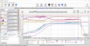
well simulation produces pretty graphs. Here is one built on readl measurement data - my synergy mids with the mic right at the center of the mouth of the horn.

My old measurement was taken only 200 to 2000 hz so we see artifacts of that in the graph. By the way, the final prediction has a near perfect impulse despite being able to see remnants of the throat reflection null in the frequency response.
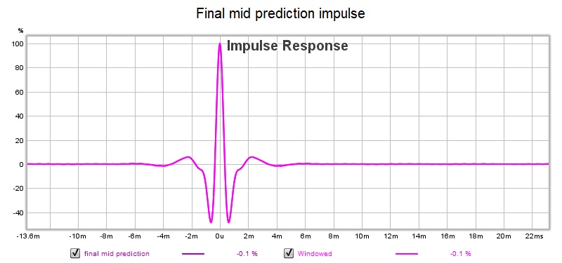
I don't imagine it would look quite so pretty if I actually implemented a new XO and took measurements but I'm not set up for that at the moment
My old measurement was taken only 200 to 2000 hz so we see artifacts of that in the graph. By the way, the final prediction has a near perfect impulse despite being able to see remnants of the throat reflection null in the frequency response.
I don't imagine it would look quite so pretty if I actually implemented a new XO and took measurements but I'm not set up for that at the moment
Attachments
Sorry Pano. I wanted a little extra width for my REW screenshot and I guess I got it. I think the software is doing rather well with it. It comes out perfectly on my smart phone and here on the computer, once I click it it just fills the screen width.
Its too late to edit now, right?
. It comes out perfectly on my smart phone and here on the computer, once I click it it just fills the screen width.Its too late to edit now, right?
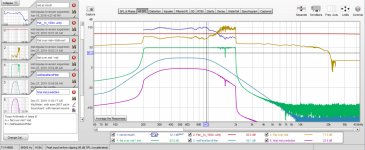
That worked as well as it did because the measurement was clean. What is the result when there is too much room in the measurement?
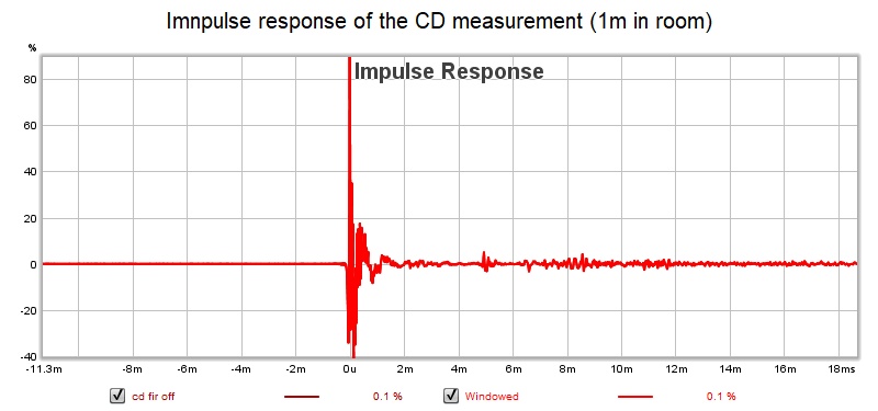
The teal trace is the final XO filter - cascade of pass band filter and CD inversion filter. Its correction is much too fine grained to be of any use. The measurement had a lot of room noise below passband in it, which might be the cause of the problem.
Need cleaner measurements!!!
The teal trace is the final XO filter - cascade of pass band filter and CD inversion filter. Its correction is much too fine grained to be of any use. The measurement had a lot of room noise below passband in it, which might be the cause of the problem.
Need cleaner measurements!!!
Attachments
- Status
- This old topic is closed. If you want to reopen this topic, contact a moderator using the "Report Post" button.
- Home
- Loudspeakers
- Multi-Way
- Measuring horn reflections back into the throat