Mark, as you noticed, there is always a difference between theory (and simulations ;-) and practical experiences in our real world of misery.A few of the "Oooh, I know electromagnetics!!" contributors here,
Reason why, sharing experiences is helpful.
Without raising our voices (level matched), writing in Braille (blind) and ensuring that several experiences do match (Double test).
The way some people, endowed with super powers, manage to read the ignored author's lips remains one of these great mysteries that science has not yet explained.But he's on your ignore list ...😛
Last edited:
Ok for the avoidance of all doubt
It sounds cleaner SUBJECTIVELY to my ears when the noise floor is -110 dB compared to -80 or -90 dB.
YMMV
It sounds cleaner SUBJECTIVELY to my ears when the noise floor is -110 dB compared to -80 or -90 dB.
YMMV
But he's on your ignore list ...😛
How do you know who I am talking about? 🙂
Here the measured IM distortion at 80Watt into 8 Ohm, very low because of the nested error correction.
The picture shows the voltage amp in the large red square and the error correction in the smaller red square above.
The BW of both voltage amp and OPS are very much larger as the first order 250KHz filter in between.
Everything is working perfectly since 2015,
Hans


Hans
The picture shows the voltage amp in the large red square and the error correction in the smaller red square above.
The BW of both voltage amp and OPS are very much larger as the first order 250KHz filter in between.
Everything is working perfectly since 2015,
Hans
Hans
Arf. Let-us try: "It sounds cleaner OBJECTIVELY to my ears".It sounds cleaner SUBJECTIVELY to my ears
What have-you done ? Reduce the levels of the signal at the input and output of the power stage, in order to can use a comparator with +-12V rails, extract the error signal and amplify-it with discrete devices (in class A) to apply it as a local feedback at the input of the OPS ?Here the measured IM distortion at 80Watt into 8 Ohm, very low because of the nested error correction.
Arf. Let-us try: "It sounds cleaner OBJECTIVELY to my ears".
😀
Some have 3rd degree burns from trying that approach here.
At the end of the day, if it sounds better to the listeners ears, they should just go with it because that’s all that counts.
If you properly bias up a conventional class AB amp using decent OPS transistors, the OL OPS distortion is remarkably low. In sims, you can easily get 0.03% at 20 kHz with say 6 pairs at 200 Watts.
If the rest of the amp OL distortion is a 100 or so ppm worst case, 50 dB of feedback at 20 kHz theoretically gets you to single digit ppm.
Obviously, 50dB of NFB @20KHz won't lower the 20KHz distortion by 50dB. To bring down an OPS distortions from 0.03% to single digit ppm one needs to look at the open loop distortion profile and design the feedback loop and the amplifier so that it has enough loop gain at 40KHz (2nd harmonic) 60KHz (3rd harmonic) etc...
Assume a great amplifier with 0.03% open loop distortion, mostly 3rd harmonic. If one needs to bring down the 20KHz distortion to 0.0005% (5ppm) and a single pole compensation schema, this would require a loop gain of about 36dB @60KHz.
Since for a two pole compensation the loop gain drops by 12dB/octave, the loop gain needs to be at least 36+18=54dB @20KHz. In simulation it's rather easy to get this, but in practice it is no small potato. Assuming an 100dB open loop gain at low frequencies,and an ideal double pole at the corner frequency, the open loop gain needs a corner frequency of 1KHz, or an open loop GBW (before applying compensation) of 100MHz. Definitely not something to be achieved with power bipolars with Ft=30MHz, and even with mosfets it's tricky (unless you accept pushing the ULGF deep into the MHz range, like Dadod did in his CFA). Sometimes I wish I had a rubber Bode diagram, with the feedback theory constraints embedded, to let people drag the diagram and intuitively see the constraints with their own eyes, without relying on algebra.
Such calculations are justifying why the PGP amp is using a 3rd order compensation network. Going to 1ppm THD20 with a standard two pole compensation is impossible with today's power devices, either bipolars or mosfets.
See, what I said, he is nice guy after all.😀
My figures were illustrative and yes I agree the distortion profile is important.
The LG BW of the practical amp I am talking about is c 8 kHz, two pole comp and a ULGF of c. 1MHz. 30-35 ppm at 200W without AFEC and 7 ppm with - I cannot measure lower.
The point is, there’s more than one way to skin a cat as we’ve seen from the numerous high performance designs on this forum.
The LG BW of the practical amp I am talking about is c 8 kHz, two pole comp and a ULGF of c. 1MHz. 30-35 ppm at 200W without AFEC and 7 ppm with - I cannot measure lower.
The point is, there’s more than one way to skin a cat as we’ve seen from the numerous high performance designs on this forum.
The LG BW of the practical amp I am talking about is c 8 kHz, two pole comp and a ULGF of c. 1MHz. 30-35 ppm at 200W
Makes sense, and I would think it's also stable in any load. Pushing much beyond this is, in practice, not realistic. Tell this to Dadod.
Which part do you want, just the error correction ?
Hans
yes, please.
-Richard
Makes sense, and I would think it's also stable in any load. Pushing much beyond this is, in practice, not realistic. Tell this to Dadod.
Why not you just build an amp with ULGF of c. 3MHz and see that it can be very stable. Or build my amp, let say 100W CFA, as many amps are built already with no complains.
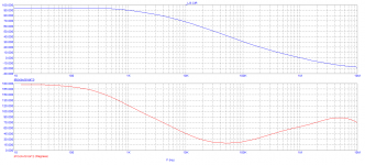
Got this (LG) as an acceptable maximum ...
Yet another guy that makes sense in this thread. Must be a full moon tonight.
Why not you just build an amp with ULGF of c. 3MHz and see that it can be very stable. Or build my amp, let say 100W CFA, as many amps are built already with no complains.
Richard's Thailand factory already built enough to illustrate. One unstable is one too many.
- Status
- Not open for further replies.
- Home
- Member Areas
- The Lounge
- John Curl's Blowtorch preamplifier part III