I think that power dissipation in resistors can be important, especially with feedback resistors, but I would not put 20 in series in order to balance the dissipation. Just use a large enough resistor for the main feedback resistor (out to input), larger than the very minimum, and use a quality 1% Dale or equivalent resistor. That is what I use. Rely on thermal capacitance primarily, rather than thermal resistance.
Richard: I was looking back through some 80's TAA mags, and there you were!
JAM has all my back issues and will make copies of each for me soon. A lot of the material and books were not able to ship to my new home in Bangkok. Cost to ship are just too high. When he copies all, we will be able to show more info to others. I had a creative spell back then and afterwards got too involved in my career and making money to write any more. But, I have always been interested in music thus audio.
-Richard
Last edited:
I am not retired...Life is good.
If what you do from 9 to 5 is fun.... it is not work.
Jn
🙂 😎

I have not had a 9-5 job for 23 years now. Its all good. My 3rd retirement. Just coasting to the inevitable oblivion now.
Going to go hang with my ladies, Lisa and Sara, in Danang next month.
-RNM
Last edited:
Yes, I am very jealous. Thanks for identifying yourself as yet another supporter of Richard’s business model.
I do not care about Richard business or someone else business.
But you did not qualify to comment about an amplifier design 😀 😀 😀
Tourny,
If you place the 20 resistors side by side (JN technique) and then have the connection essentially zig zag the the inductance will be reduced. That yields the best result. I would use the Dale metal film resistors. The power rating of the stack should be at least four times what the actual peak dissipation could be.
Another issue is that the value of the single resistor should be equal to the resistor on the source input side of a differential pair.
Some here would try the input side resistance as high as 100,000 ohms. I would use 10,000 ohms. With a normal 20/1 attenuator that would make the feedback resistor 200,000 ohms.
Even with 1/10 watt power rating of some surface mount resistors that would allow your power supply rails to be several hundred volts!
JC would probably prefer a lower resistance value to avoid the effects of stray capacitance and as he uses a DC servo matching resistances on both sides of the differential pair is not as important.
But you did not qualify to comment about an amplifier design
No, I am not
. Thanks God we have Richard, yourself and a few others here to enlighten the unwashed masses of the the high end SOTA audio amplifier design whereabouts.Why do you make up this crap?
-RNMarsh
Do I? I thought I quoted your very own posts. “Click” is your friend (or enemy, in this case
)Nice idea: Surface mount in zig-zag serial look, indeed, a good option.Tourny,
If you place the 20 resistors side by side (JN technique) and then have the connection essentially zig zag the the inductance will be reduced. That yields the best result. I would use the Dale metal film resistors. The power rating of the stack should be at least four times what the actual peak dissipation could be.
Another issue is that the value of the single resistor should be equal to the resistor on the source input side of a differential pair.
Some here would try the input side resistance as high as 100,000 ohms. I would use 10,000 ohms. With a normal 20/1 attenuator that would make the feedback resistor 200,000 ohms.
Even with 1/10 watt power rating of some surface mount resistors that would allow your power supply rails to be several hundred volts!
JC would probably prefer a lower resistance value to avoid the effects of stray capacitance and as he uses a DC servo matching resistances on both sides of the differential pair is not as important.
The inductance is reduced, the voltage on each as well.
My question is general. But in, my particular case, I'm in the worse situation: It is a CFA: 750 Ohms serial. ~30dB gain.
Why 4X the peak dissipation ? There is ~10db of dynamic margin VS average musical level and it is a ~200W amplifier. I doubt it will be used at full power. So I thought just the resistances have to survive at a DC rail if one power device burn in short circuit. Am-I wrong ?
Last edited:
Have fun, as habit. You are definitely helpful and sym-pathetic.
You may wonder, but the Earth magnetic field effect on the audio gear placement was invoked here, years ago, by a famous designer that should now remain unnamed. If curious, the forum search engine is your friend.
You should always trust and follow those famous designers
.Ergo, the need to control bias during listening comparison of audio components.Show me a person without bias and I will show you a person without an opinion. Ergo, those who accuse you of bias has expressed an opinion, glass houses and all that. 😉
No, I am not
People can decide by them self about good amplifier for them. It is not depend on Richard opinion.
Tourny,
At 1/4 power the distortion drops 1/16. That makes it almost unmeasurable. I would look at the PCNM series power thin film surface mount resistors. A 1/4 watt power rating using 31 resistors should work well.
At 1/4 power the distortion drops 1/16. That makes it almost unmeasurable. I would look at the PCNM series power thin film surface mount resistors. A 1/4 watt power rating using 31 resistors should work well.
Sorry, It is not because I 'listen' as much as I measure that i'm a believer or a snobbish. I just try to be open minded. When something do not look stupid, I verify if I can hear an 'obvious' difference.You should always trust and follow those famous designers
Somebody, long time ago, was trying to "sell" me those magical cones under amplifiers.
So I recorded my amp with a tone and hitted-it with a hammer. Nothing, end of the story. But it was not impossible, in my mind, that some components should be microphonic.
About magnetic effects in power amps, the position of the output coil is measurable.
And, may-be, a difference between aluminium and steel enclosures, but I never tried a comparison. Do-you have an opinion ?
Or do-you think everything sound the same, topologies, fet VS bipolar in inputs and output stages, capacitances etc ?
Et pourquoi tant de haine ?
Last edited:
Did-you verified by yourself, Simon ? (not that I don't believe-you ;-) but I think my actual measuring equipment would not be good enough to make the difference.At 1/4 power the distortion drops 1/16.
Thank-you a lot, you are, as often, very helpful.
Nice idea: Surface mount in zig-zag serial look, indeed, a good option.
The inductance is reduced, the voltage on each as well.
My question is general. But in, my particular case, I'm in the worse situation: It is a CFA: 750 Ohms serial. ~30dB gain.
Why 4X the peak dissipation ? There is ~10db of dynamic margin VS average musical level and it is a ~200W amplifier. I doubt it will be used at full power. So I thought just the resistances have to survive at a DC rail if one power device burn in short circuit. Am-I wrong ?
******* use 3 of these WNE250FET Ohmite | Mouser Canada in series and be done with it. Saves space, money, they are non inductive, 20ppm/C temperature coefficient, and wire wound resistors have virtually zero voltage coefficient.
Yes, I know, I just spoiled your fun
.I verify if I can hear an 'obvious' difference.
You should tell that to Markw4 for his DAC sound claims.Did-you verified by yourself, Simon ? (not that I don't believe-you ;-)
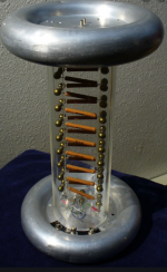
Resistors have shunt capacitance as well as inductance and at 10K the cap dominates. It seems they tend to balance ot around 100 Ohms but nothing is guaranteed. If you are looking for precision you do want a pretty high power resistor divider and if the ratios can work the nonlinearities "may" cancel or they may add. My AC calibrator uses a 5W Vishay foil in its feedback to meet the performance requirements for 10V.
The photos are high voltage precision dividers showing some of what is involved to get accuracy for HV AC. The better ones I have seen spiral the resistors as you can see.
The photos are high voltage precision dividers showing some of what is involved to get accuracy for HV AC. The better ones I have seen spiral the resistors as you can see.
Attachments

Thanks for that, it hit the spot.
😀 It's one of those albums that really grows on you.
That's true, I'm listening to the world's first high end CMA at this very moment.People can decide by them self about good amplifier for them. It is not depend on Richard opinion.
Ce n'est pas parce qu'il y a marqué "bénédictine" sur la porte des chiottes que c'en est ! ©André PousseThey are non inductive
It is not because there is written "Bourbon" on the door of the toilet that it is.
I will not take the risk.
Damir’s amp is free. I think you are jealous because you can not design an amp as good as Damir’s amp 😀 😀 😀
Thanks Bimo, but you are wrong, syn08 can design an amp, look his web page,
Home, he is just that kind of guy, likes to provoke others.
- Status
- Not open for further replies.
- Home
- Member Areas
- The Lounge
- John Curl's Blowtorch preamplifier part III