So a while ago I designed and made up a little pcb with 6 NE5532's (TI branded), constituting 1 non-inverting buffer then 11 unity-gain inverting stages. The idea was to purely test the cumulative effect of 12 opamps.


Recently I've actually got some equipment (Focusrite Scarlett Solo) that can have a stab at decent measurements of the setup.
I generated various test signals as WAV files including a six-tone (non-harmonically related) intermodulation test signal, which is somewhat closer to a typical music signal than a single 1kHz tone:


The comparison with a loopback and the string of 12 NE5532 stages is quite revealing:


The few places the green NE5532 plot emerges above the loopback plot seems to be a 16kHz spur (presumably ADC or DAC artifact), and the mains harmonic noise at low frequency (the setup is not screened and strewn across the desk alas).
The tiny peaks present in both the loopback and NE5532 output are presumably due to quantization of the WAV file, they are IM products at low levels I think.
So the performance of the Scarlett Solo is insufficient to distinquish 12 opamps in a row from a piece of wire. Or put more positively NE5532's are hard to beat.
There is a possibility some of the LF spurs are frequency difference peaks, but there's no evidence of 2nd order frequency-sum spurs or of 3rd order spurs above the noise-floor.
I was recording at 96kSPS and 24 bit, I think the waveform file may be 16 bit though. The amplitude was a moderate line-level, I forgot to make a note of it alas.
I post-processed the output using Python's scipy.signal library to normalize the levels and compute the spectrum (using the scipy.signal.welch function), and employed a very accurate flattop window to ensure the peak heights were right, its the HFT144D window from this excellent paper: https://holometer.fnal.gov/GH_FFT.pdf
I realize in retrospect I should have made jumpers on the board to allow more stages to be non-inverting and thus subject to common-mode distortion, not just the first buffer, as that would be an interesting comparison.
Recently I've actually got some equipment (Focusrite Scarlett Solo) that can have a stab at decent measurements of the setup.
I generated various test signals as WAV files including a six-tone (non-harmonically related) intermodulation test signal, which is somewhat closer to a typical music signal than a single 1kHz tone:
The comparison with a loopback and the string of 12 NE5532 stages is quite revealing:
The few places the green NE5532 plot emerges above the loopback plot seems to be a 16kHz spur (presumably ADC or DAC artifact), and the mains harmonic noise at low frequency (the setup is not screened and strewn across the desk alas).
The tiny peaks present in both the loopback and NE5532 output are presumably due to quantization of the WAV file, they are IM products at low levels I think.
So the performance of the Scarlett Solo is insufficient to distinquish 12 opamps in a row from a piece of wire. Or put more positively NE5532's are hard to beat.
There is a possibility some of the LF spurs are frequency difference peaks, but there's no evidence of 2nd order frequency-sum spurs or of 3rd order spurs above the noise-floor.
I was recording at 96kSPS and 24 bit, I think the waveform file may be 16 bit though. The amplitude was a moderate line-level, I forgot to make a note of it alas.
I post-processed the output using Python's scipy.signal library to normalize the levels and compute the spectrum (using the scipy.signal.welch function), and employed a very accurate flattop window to ensure the peak heights were right, its the HFT144D window from this excellent paper: https://holometer.fnal.gov/GH_FFT.pdf
I realize in retrospect I should have made jumpers on the board to allow more stages to be non-inverting and thus subject to common-mode distortion, not just the first buffer, as that would be an interesting comparison.
Last edited:


Impressive ... given a project I'm just starting, very good to know.
So, why are people constantly swapping them out of amplifiers?
So, why are people constantly swapping them out of amplifiers?
That's easy, because they hear a difference, it's very difficult to swap op amps without knowing you've done it.
That's easy, because they hear a difference, it's very difficult to swap op amps without knowing you've done it.
But, is there an actual difference, or is it imagined?
Or maybe it's worse... In This Thread we saw the kinds of problems it can cause.
As Mark has pointed out in still other threads, often a circuit is designed around specific behaviour of a particular opamp... slew rate, input impedance, output drive, etc... and swapping in other chips can cause some very strange behaviour.
I would almost pay to see a blind AB comparison between two identical devices, one with the chips swapped, the other factory, and see if anyone can reliably pick the modified device as sounding better (or worse).
Last edited:
As you say, it could be either, the only way to get closest to the truth is to measure. We really don't just use our ears to hear. There is always going to be an element of doubt, even looking at the measurements could also have an effect on what we hear. But, measurements and techniques are getting very good indeed.
As you say, it could be either, the only way to get closest to the truth is to measure. We really don't just use our ears to hear. There is always going to be an element of doubt, even looking at the measurements could also have an effect on what we hear. But, measurements and techniques are getting very good indeed.
Our ears lie to us all the time. Confirmation Bias is a very real thing. Take the example of RCA cables... the salesmaker starts off with a cheap cable, everything sounds okay, then he puts in his magic expensive cable: "Now listen to how this opens up the sound state and how much more detail there is" and sure enough everyone notices it... because they were told to. Put those same two cables through a Null Test and you won't find a single bit of difference.
The lesson is that we can't trust our ears, when there are expectations involved.
I'm impressed to see that signal go through 20 op-amps and come out the other end totally unscathed... but I'm not surprised.
It's not the ears that lie, it's merely the brain filling in the blanks. It does this with all our senses.
Maybe it just goe to show that, 42 years later, the venerable NE5532 is still one of the best opamps ever made. An LM4562 (or others) may be able to beat it on some tests, but are they audibly better? Perhaps not. And they're a bargain these days at only $1 apiece!
Our senses have evolved together as an aid to survival, our brain has to take all this information as well as experience and create a version of reality that hopefully means it will live another day. Now I'm not saying the salesman is a threat but our primordial self doesn't know that 😉Take the example of RCA cables... the salesmaker starts off with a cheap cable, everything sounds okay, then he puts in his magic expensive cable: "Now listen to how this opens up the sound state and how much more detail there is" and sure enough everyone notices it... because they were told to.
And they're a bargain these days at only $1 apiece!
I've seen them listed as low as $0.35 in Canadian funds.
Our senses have evolved together as an aid to survival, our brain has to take all this information as well as experience and create a version of reality that hopefully means it will live another day. Now I'm not saying the salesman is a threat but our primordial self doesn't know that 😉
And boy oh boy do they capitalize on it. My friend calls it "predatory marketing" and I am forced to agree.
I was actually quite surprised when I joined here and found all these threads about swapping out perfectly good parts. Not at all what I expected.
Last edited:
I was actually quite surprised when I joined here and found all these threads about swapping out perfectly good parts. Not at all what I expected.
I know what you mean
An interesting ethical question: which is more dishonest/reprehensible, selling a "discrete opamp" which is just window dressing around a real NE5532, or selling a discrete opamp which has poorer specs but claiming its somehow more special?
Got round to some two-tone testing with the same setup, this time at a range of output levels, both in loopback and through the 12 opamp chain. The higher output levels ('medium' and 'loud' in the filenames) show the expected IM product spurs, and in some of them the opamp distortion is clearly present as the spurs are definitely higher. The lowest output level graphs produce less distortion but the noise floor is higher (hiding the actual spurs), again as expected.

And zoomed in to see the levels within the peaks a bit more clearly:

And this time I made sure the source was 24 bit WAV file.

The white wedge at the bottom of the twin peaks is an artifact of the HFT144D window - it starts to broaden significantly from -144dB down.
And zoomed in to see the levels within the peaks a bit more clearly:
And this time I made sure the source was 24 bit WAV file.
The white wedge at the bottom of the twin peaks is an artifact of the HFT144D window - it starts to broaden significantly from -144dB down.
Last edited:
You'd have to ask the Righteous Brothers, and see how this sounds through the chain YouTubeAn interesting ethical question: which is more dishonest/reprehensible, selling a "discrete opamp" which is just window dressing around a real NE5532, or selling a discrete opamp which has poorer specs but claiming its somehow more special?
But, is there an actual difference, or is it imagined?
Or maybe it's worse... In This Thread we saw the kinds of problems it can cause.
As Mark has pointed out in still other threads, often a circuit is designed around specific behaviour of a particular opamp... slew rate, input impedance, output drive, etc... and swapping in other chips can cause some very strange behaviour.
I would almost pay to see a blind AB comparison between two identical devices, one with the chips swapped, the other factory, and see if anyone can reliably pick the modified device as sounding better (or worse).
Hi
I have now a setup that can switch between 3 opamps installed as an output filter of the same DAC (AK4497). The DAC+/DAC- go to the 3 identical low pass filters and the output of the filters (using different opamps) is selected by relays as in a preamp selector using a simple knob.
Test results:
1) my wife detects the differences after about 2 seconds on acoustic music. And she does not know which one is selected (she has no idea what i am switching anyway...).
2) my fiend took about 5 seconds to identify the difference between opamp #1 and #2 but not sure about the 3rd one. It was rock music used this time.
3) of course I can hear the differences too but not on all music and not easily as my wife.
The 3 opamps are VFB types and indicated for audio applications from the datasheet .
I am not claiming anything but just reporting a free A/B test result.😉
Fab
Last edited:
I'd be quite leery of any NE5532 priced that low. There have been many stories of different-branded "NE5532" opamps that spec'd and sounded quite different. One fellow even reported that he had been hired (by the manufacturer) to change out over 800 NE5534 op amps in a mixing console because they were substandard in performance to the real ones.I've seen them [NE5532] listed as low as $0.35 in Canadian funds.
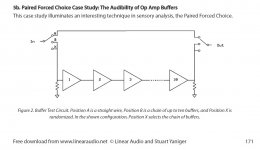
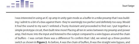
SY performed something similar to this some years back, it begins on page 171 here (and there are lots more goodies in this pdf):
http://linearaudio.net/sites/linearaudio.net/files/LA Vol 2 Yaniger(1).pdf
http://linearaudio.net/sites/linearaudio.net/files/LA Vol 2 Yaniger(1).pdf
Attachments
Thanks for sharing the study. I do not want to discredit the study which shows interesting aspects to consider but as any study it has limitations. The repeatability of the results of the blinded test with the same subjects at different moment would be more important I believe. Personally there are some opamps I can not hear the differences too depending on the music content, other pieces in the system or I do not have the capacity to differentiate them. However I can admit that others my have better audio capacity than I have. Similar to identify different wines taste...
A most revealing test is to compare OPA1611 and OPA1641 which have the same schematics as per TI except that 1611 has bipolar transistors for differential input stage and 1641 has Jfet instead of bipolar as input. The difference is very obvious for most recordings.
Fab
A most revealing test is to compare OPA1611 and OPA1641 which have the same schematics as per TI except that 1611 has bipolar transistors for differential input stage and 1641 has Jfet instead of bipolar as input. The difference is very obvious for most recordings.
Fab
Last edited:
- Home
- Source & Line
- Analog Line Level
- 12 opamps chained - measurements