Jim you're always welcome for a listen up in Sheffield. We can rustle up 2 different sets of lundahl or the op amp stage.
If you do use the transformers you can pull batteries from the opamp rails and use them as two additional rails for the dac. Most worthwhile
If you do use the transformers you can pull batteries from the opamp rails and use them as two additional rails for the dac. Most worthwhile
Simon I heard your tomchr amps at an MCRU open day a while ago. I thought they bested the mega bucks stuff on show that day....so I do value yours and mister dogs implementations.
Hopefully we can meet up sometime soon
Hopefully we can meet up sometime soon
Perfboard Pitch
Hello all,
Is there any perfboard available that does not have a hole pitch of 2.54mm? Ideally, I need a pitch of around 3.40mm.
Hello all,
Is there any perfboard available that does not have a hole pitch of 2.54mm? Ideally, I need a pitch of around 3.40mm.
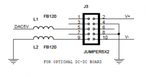
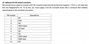
Optional DC/DC converter on Standard I/V board
If somebody plans to use the DC/DC converter socket on the Standard I/V board, follow the pin designations in the schematics. I believe those indicated in the manual are wrong.
Note that current is taken from the FIFO rail (not the RPi rail) so beware that you might only have 3.3V available if you are using batteries direct to supply the FIFO.
Attachments
question regarding dual es9038Q2M dac hat
does each es9038q2m relate to single channel or dac chips are In parallel
are all output signals L, LB, R, RB from each es9038q2m routed to output connector
does each es9038q2m relate to single channel or dac chips are In parallel
are all output signals L, LB, R, RB from each es9038q2m routed to output connector
Ian, have you just bent their legs or elongated as well.
Cheers , Ernst
@ernesternest
My Transformer I/V II PCB has footprint to fit those transformers. Will work right away.
Don't bend the legs because the coil wires are very thin and easy to get damage internally.
Regards,
Ian
question regarding dual es9038Q2M dac hat
does each es9038q2m relate to single channel or dac chips are In parallel
are all output signals L, LB, R, RB from each es9038q2m routed to output connector
@samoloko
Two ES9038Q2Ms, one for left channel and the other one for right channel.
That's the mono block, not the parallel.
Regards,
Ian

thank you for Illustration
Ian,
would you please confirm exact routing of 4 outputs per es9038q2m
can I take all 4 outputs per every chip from connector
Last edited:
thank you for Illustration
Ian,
would you please confirm exact routing of 4 outputs per es9038q2m
can I take all 4 outputs per every chip from connector
@samoloko,
What bisesik posted is correct. Please see the above drawing.
@ bisesik
Thanks!
Ian
I received the ReceiverPi yesterday and have now tested the basic functionality.
Needless to say - it works perfectly. Great stuff Ian!
There is one thing I would like to do, but that I cannot figure out how to implement:
When I'm listening to sources not coming from the RPi, i.e. those interfaced by the ReceiverPi, I would like to power the RPi off as it is probably the worst noise source around. Fortunately Ian has made this simple to do using the optional power input on the Receiver module. If this power input is used (with L1 removed) ReceiverPi is powered without also powering RPi (via GPIO). However, a side effect at not powering the GPIO is that the ESS Controller is also not powered anymore....
I can probably just moveESS Controller to the isolated side, but that means adding a new potential source of noise. Hardly the objective.
Any suggestions on how to make it work without moving the ESS Controller to the clean side? I guess what I need is some way to power the ESS Controller without powering RPi. Or some way to shut down RPi even if it is powered.
Any input is very welcome!
Nic,
what Is your recomendation for min setup using RPI
Is fifopi essential - can I use DAC Hat In sync mode without It
about receiver pi - can we control receiver Pi Inputs using ESS controler
can you show us your stack
what Is your recomendation for min setup using RPI
Is fifopi essential - can I use DAC Hat In sync mode without It
about receiver pi - can we control receiver Pi Inputs using ESS controler
can you show us your stack
I received the ReceiverPi yesterday and have now tested the basic functionality.
Needless to say - it works perfectly. Great stuff Ian!
There is one thing I would like to do, but that I cannot figure out how to implement:
When I'm listening to sources not coming from the RPi, i.e. those interfaced by the ReceiverPi, I would like to power the RPi off as it is probably the worst noise source around. Fortunately Ian has made this simple to do using the optional power input on the Receiver module. If this power input is used (with L1 removed) ReceiverPi is powered without also powering RPi (via GPIO). However, a side effect at not powering the GPIO is that the ESS Controller is also not powered anymore....
I can probably just moveESS Controller to the isolated side, but that means adding a new potential source of noise. Hardly the objective.
Any suggestions on how to make it work without moving the ESS Controller to the clean side? I guess what I need is some way to power the ESS Controller without powering RPi. Or some way to shut down RPi even if it is powered.
Any input is very welcome!
Hi NicMac,
Your requirement is interesting. But I have solution.
You can cut all of the 5V pins on the RPi GPIO but keep L1 of ReceiverPi without removing. Both ReceiverPi and ESS controller can be powered from FifoPi in this case.
However you still can if you really want the ReceiverPi having independent power with L1 removed, ESS controller will still have power from FifiPi in this case.
Regards,
Ian
Thanks Ian,
I made it work cutting the 5V GPIO pins and recreating the connection with a switch. Now I can turn off RPi alone, which is what I want to do when I use ReceiverPi inputs.
New question. I noticed that whichever sample rate of SPDIF I'm feeding the ReceiverPi the ESS controller display indicate: 96kHz, 6.1440MHz, I2S, 32b
Can this be changed? For example to 192kHz, 16b
Can this be changed? For example to 192kHz, 16b
I have a question. I want to run my 45 clock on its own 3.3v rail. I am currently using NDK SDA on an adapter board.
Do I replace pin 4 with 3.3v rail and leave PSU Ground unconnected and keep it on the same ground plane as the FIFO.
Or should I replace Pin 2 (ground) and Pin 4 (VCC) with the 3.3v rail on the adapter board?
Do I replace pin 4 with 3.3v rail and leave PSU Ground unconnected and keep it on the same ground plane as the FIFO.
Or should I replace Pin 2 (ground) and Pin 4 (VCC) with the 3.3v rail on the adapter board?
I have a question. I want to run my 45 clock on its own 3.3v rail. I am currently using NDK SDA on an adapter board.
Do I replace pin 4 with 3.3v rail and leave PSU Ground unconnected and keep it on the same ground plane as the FIFO.
Or should I replace Pin 2 (ground) and Pin 4 (VCC) with the 3.3v rail on the adapter board?
The first. If clock GND is not connected to FIFO GND in some way it should not work.
I'm using a 3V3 shunt reg with Vin and GND pins connected to the 5V FIFO supply header (fed with 5V from a linear supply) and the third leg (Vout) connected to clock VCC, with the VCC pin on the clock adapter board cut. Works perfectly.
Thanks NicMac, much appreciated.
I am planning to use the Ian's Battery PSU so its a single isolated rail. What would you suggest I do with the excess GND of the clock rail?
- Home
- Source & Line
- PC Based
- IanCanada's Latest RPi GB Goodies Impressions... and your tweaks, mods and hints...