I have just checked the 337, and to be stable it requires at least 10µF of output capacitance.Today I tested the LM337 + D-N with only a 100nF ceramic straight at the output, and again the same instability as with the 1uF. Pretty remarkable , it just doesn't want to play ball with a ceramic cap , not even a small one.
If you're like me wanting (wanted) to use the "D-Noizator: a magic active noise canceller to retrofit & upgrade any 317-based V.Reg" , in existing circuits , like preAmps , HPamps based on Elektor designs , you might want to check first for ceramic cap's or even low ESR E-caps at the LM's output. While you think to make it better with the DeNoiser , could be you actually make it far worse , especially with the LM337. So test it before you make changes that are hard to turn back.
Of course , me changing some values of resistors to have a low current version, may have played a role, but my values are about double the Elvee ones and he tested it with values 5 times as high.
Just finished my 4 DeNoisers today , putting 18V zeners and 1N5819 over the outputs and still works fine (without ceramics) , just with 100uF .
IIRC, the 317 was stable with less than 1µF, so the negative version is somewhat more finicky than the positive one.
These tests are made on a breadboard, which probably contributes to the instability: when I add a more direct bypass cap at the input, matters improve somewhat.
I added protection diodes for Khadgar's application and I updated the circuit to make it compatible with a 337 by increasing the compensation cap to 10n and eliminating the series resistance that the 337 does not like.You did change the original circuit's DeNoiser add-on.
No, certainly not: there must be something wrong somewhereFirst tests I have been doing seem to show PSRR is unaffected by input voltage filtering. It doesn't change a bit. Is that so?
No, certainly not: there must be something wrong somewhere
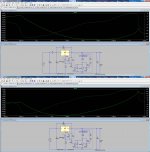
Of course you were right. Here's the DeNoiser later version's PSRR.
One with 100uF input filter cap, and the other with a CRC, increased capacitance filter.
Attachments
EUREKA!!!
I changed resistors for biasing DN BJT and everything looks so smooth on oscilloscope. From 1.2V up to 29V when LM317 starts to stop regulating cause of low dropout voltage. Ofc probably DN doesn't work good on low voltages but this was just meant to be small one day project to see how DN works and to have something better then regular LM317 psu on workbench.
Ofc that CCS is disconnected cause he also cause oscillations even with right value resistors.
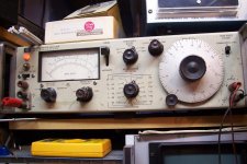
I dont have some sensitive voltmeter but i have HP334A that can measure up to 30uV full scale so i will see how much noise i get from my "version" of DN.
EDIT, no i won't connect to HP334A cause it doesn't have AC/DC switch... 😡
I guess i'll just have to trust that DN works as intended. I can ofc try check on oscilloscope(5mV/div) how it behaves when i connect different loads but that's it.
I changed resistors for biasing DN BJT and everything looks so smooth on oscilloscope. From 1.2V up to 29V when LM317 starts to stop regulating cause of low dropout voltage. Ofc probably DN doesn't work good on low voltages but this was just meant to be small one day project to see how DN works and to have something better then regular LM317 psu on workbench.
Ofc that CCS is disconnected cause he also cause oscillations even with right value resistors.
I dont have some sensitive voltmeter but i have HP334A that can measure up to 30uV full scale so i will see how much noise i get from my "version" of DN.
EDIT, no i won't connect to HP334A cause it doesn't have AC/DC switch... 😡
I guess i'll just have to trust that DN works as intended. I can ofc try check on oscilloscope(5mV/div) how it behaves when i connect different loads but that's it.
Last edited:
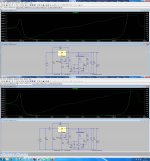
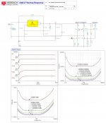
Denoiser's latest version impedance comparison.
The difference is only on the input filter: 100uF on one and CRC on the other.
Contrary to my expectations, the CRC version's impedance has a slight peak on the right, but the curve that really matters is less than 65 microohms from 3Hz to 10KHz. Which I think is great.
The CRC version had better PSRR response than the single cap filter version.
The first DeNoiser version's impedance was about the same.
Please have look and tell me the setup looks fine.
Attachments
Now that i have DN working i'm hoping that my friend from other forum will find some time and test it in practice with spectral analyzer up to 10MHz. If he does i'll post results here.
Don't worry about the 334: like all similar instruments, it is AC-coupled by construction. I know, I also have one:I dont have some sensitive voltmeter but i have HP334A that can measure up to 30uV full scale so i will see how much noise i get from my "version" of DN.
EDIT, no i won't connect to HP334A cause it doesn't have AC/DC switch... 😡
I guess i'll just have to trust that DN works as intended. I can ofc try check on oscilloscope(5mV/div) how it behaves when i connect different loads but that's it.
That said, it won't tell you a lot: it would already reach its limits with a 317 without additional caps, and with caps or the denoiser, it will be practically useless.
You need a LNA in front of it to be able to see something.
It can be as simple as a good opamp wired as X10 amplifier. If you have nothing better, even a NE5534 will already let you see something, but a superopamp like the LM4562 or AD797 would be preferable
Attachments
Are you sure the peak is on the right? I see a peak on the left for both, which is normal because the input and output poles are located a bit close.Contrary to my expectations, the CRC version's impedance has a slight peak on the right, but the curve that really matters is less than 65 microohms from 3Hz to 10KHz. Which I think is great.
It is a tradeoff, magnified by the linear scale and it does no actual harm, but if it is a problem for you, you can split them further apart by increasing C3 (this will also increase the startup time), or decreasing C2 (it will reduce the VLF response).
You are of course free to opt for another tradeoff
Last edited:
Yeah i checked service manual and saw it's AC coupled. I'll connect to it anyway just to check if i didn't messed up layout or that extra 2n2955 is making any noise.
I'll check what kind of OPamps i got at home and maybe i'll build some nice compact smd design which PCB can be connected directly to 334A so only wires would be from device under test.
I'll check what kind of OPamps i got at home and maybe i'll build some nice compact smd design which PCB can be connected directly to 334A so only wires would be from device under test.
Are you sure the peak is on the right? I see a peak on the left for both, which is normal because the input and output poles are located a bit close.
It is a tradeoff, magnified by the linear scale and it does no actual harm, but if it is a problem for you, you can split them further apart by increasing C3 (this will also increase the startup time), or decreasing C2 (it will reduce the VLF response).
You are of course free to opt for another tradeoff
😀
Of course it's on the left.
No problem for me. The frequency the peak is at it is inaudible.
Though increasing the startup time seems interesting, anyway. What would be a good value for C3?
Last edited:
I found OPA211 and by looking at datasheet that would be nice for LNA. Just need to make some nice PCB with smd parts and i'm ready for measurement, and ofc some psu for this board.
Maybe i could find some +/-15V inside 334A and use it to power LNA. 😀
Maybe i could find some +/-15V inside 334A and use it to power LNA. 😀
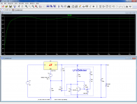
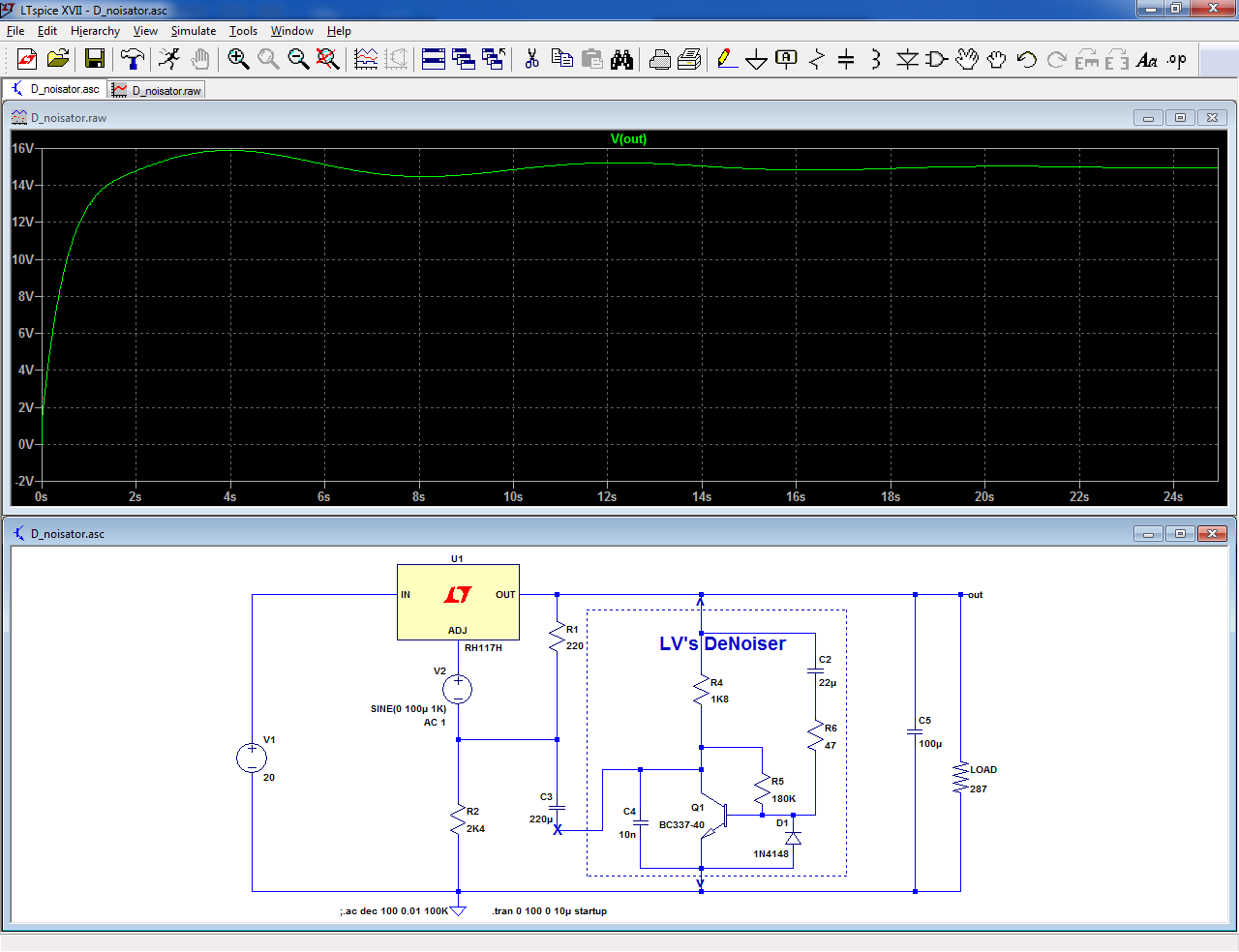
This has already been evoked earlier in the thread, but basically it is a matter of taste: personally, I already find the ~10s stabilization time of the current version borderline annoying, but other people differ.Though increasing the startup time seems interesting, anyway. What would be a good value for C3?
This is the startup of the present tradeoff, but seeing it in a sim and experiencing it in reality are two different things:
A lot also depends on what the supply is connected to: if your preamp takes a further 20s to settle after the supply has completely stabilized, it will feel like a long time.
Some circuits may already work quite well before the complete stabilization, making the startup time more or less irrelevant
Attachments
Btw about simple LNA,i couldn't find what's input impedance of 334A but i guess since it has 300uV range(i made mistake saying it's 30uV) i guess single OPamp wired as 10x amplifier without buffer is good enough?
I searched my stash and found that i have LM4562(dual OPamp) so i can make 10x amp-buffer combination if needed.
I searched my stash and found that i have LM4562(dual OPamp) so i can make 10x amp-buffer combination if needed.
This has already been evoked earlier in the thread, but basically it is a matter of taste: personally, I already find the ~10s stabilization time of the current version borderline annoying, but other people differ.
This is the startup of the present tradeoff, but seeing it in a sim and experiencing it in reality are two different things:
A lot also depends on what the supply is connected to: if your preamp takes a further 20s to settle after the supply has completely stabilized, it will feel like a long time.
Some circuits may already work quite well before the complete stabilization, making the startup time more or less irrelevant
Now I realize that what I was thinking would be better to achieve was exactly the opposite that I said.
What I would like to is to shorten the startup time, not to lengthen it.
OTOS I usually do not turn off low current equipment, I leave it on all the time. So in the end the only things that matter most is how audio quality is affected, and settling time is not important really.
Hey Elvee , can you be super clear about the 33 ohm R in series with the 10nF used with LM317 and LM337. I'm about to solder the DeNoiser PCB to the CRC/switch PCB , and because it is in a vertical position , it will be imposssible (or a BIG pain) to reach it with the soldering iron or disconnect the little board again with the thick copper rods.
In stead of getting out the 33 , maybe put another one over it , to make it 16,5 ohm ?
What's the worst that can happen letting the 33's in there ? Another instability ?
In stead of getting out the 33 , maybe put another one over it , to make it 16,5 ohm ?
What's the worst that can happen letting the 33's in there ? Another instability ?
Wire a 4562 in X100 mode, that will give you 3µV fsd, and use a 51 ohm resistor at the output, to cope with the capacitive load (put everything in a metal box with a separate supply)Btw about simple LNA,i couldn't find what's input impedance of 334A but i guess since it has 300uV range(i made mistake saying it's 30uV) i guess single OPamp wired as 10x amplifier without buffer is good enough?
I searched my stash and found that i have LM4562(dual OPamp) so i can make 10x amp-buffer combination if needed.
For the 317, a 33 ohm resistor either does nothing, or improves the stability in some situations (but a 317 can always dispense with it).Hey Elvee , can you be super clear about the 33 ohm R in series with the 10nF used with LM317 and LM337. I'm about to solder the DeNoiser PCB to the CRC/switch PCB , and because it is in a vertical position , it will be imposssible (or a BIG pain) to reach it with the soldering iron or disconnect the little board again with the thick copper rods.
In stead of getting out the 33 , maybe put another one over it , to make it 16,5 ohm ?
What's the worst that can happen letting the 33's in there ? Another instability ?
The 337 does not tolerate resistance at all.
This is why I "unified" the schematic: it is now valid for both polarities, but if you have 33 ohm in your 317's, you can leave them in place.
For the 337, they should be removed
Damn, was hoping to do some OPA211 smd soldering but if you say 4562 is better then i'll do that. I think i'll probably do 100x and 10x options jumper selectable. So since 4562 is dual, i'll use one for amplifier and other one i'll just ground it.
I got some thin copper sheets that i can probably use to shield this LNA.
Btw i don't even need to say that socket for 4562 is out of the question,right?
I got some thin copper sheets that i can probably use to shield this LNA.
Btw i don't even need to say that socket for 4562 is out of the question,right?
Ok, thanks LV.
I'll remove the ones with the LM337.
You say : "The 337 does not tolerate resistance at all." , but after removing the ceramic cap , everything seems ok . could the 33 be the cause of the instability with the ceramic cap ?
I'll remove the ones with the LM337.
You say : "The 337 does not tolerate resistance at all." , but after removing the ceramic cap , everything seems ok . could the 33 be the cause of the instability with the ceramic cap ?
This are two schematics that member on our local forum simulated in TinaTI. Simpler one got current mirror and extra BJT for fast startup. Other one got same but has been modified to be lab supply.
Lab supply circuit has been made and tested on workbench and shows no sign of oscillations.
This is the forum LAB PSU 0-30VDC, 0-500mA/0-5A but it's kinda closed, you can see some topics and some you can't without signing up.
Btw i'm just messenger so if something goes wrong if you plan ti build it don't kill me. 😛
Attachments

The second one is really a very complicated power supply.
I'd keep with the Jung superregulator.
I'd keep with the Jung superregulator.
Second one is meant to be fully functional workbench power supply.
First one is designed to it can work really good even on low output voltages where simple resistor biasing of denoiser BJT won't work very well,but needs some sort of negative aux voltage.
@Elvee if you think this is a bit offtopic i'll stop here with this modified denoiser versions. I just wanted to show that we are all grateful that you got this idea so we we're playing around it to see if we can improve it a bit as stand alone PSU.
- Home
- Amplifiers
- Power Supplies
- D-Noizator: a magic active noise canceller to retrofit & upgrade any 317-based VReg