Thanks for reporting the issue: one can never be sure until a test is actually made.I trusted the "in principle the DeNoiser will work with LM337 and other
regulators", so I didn't test them and made a PCB . I was wrong. With the
DeNoiser , having more than a couple of 10's mA load , the output dropped , and dropped
more with higher loads . Going back to no load , the output snaked again around
the right output voltage like switching on. Both LM337's did exactly the same. No
amount of capacity at the input and/or output helped and yes I checked polarity of
the caps of the D-N , PNP transistor . I didn't check twice , I did it multiple times
and of course during the PCB design stage. Freq counter didn't detect oscillation .
When I short the CE of the transistor , all is normal , working like there is no
DeNoiser , shorting the diode over BE did the same.
That's where I'm at. No critism on Elvee , the title says DeNoiser for LM317, but if you use it for audio upgrades , where there are - and + supplies , you might make things a lot worse if
the D-N isn't playing well with the existing LM337.
Now I'm thinking of only using the D-N with the LM317 and use the LM337 with
just the Ref cap . Seriously disappointed , opamps's PSRR is always worst to the
neg supply. Using a LM317 for both sides is not posible because they have a shared
ground and PCB is already made and too compact to change and I don't like the
ground interupted by a regulator. My ground (0) goes straight from the transformer
with thick copper to the CRC and regulators to the amp PCB.
So be warned and test your circuit before making a PCB and solder everything on
it.
You say that you didn't detect oscillations, yet all the symptoms seem to indicate just that: the denoiser has no effect on the DC voltage, and if does, that has to be because of parasitic oscillations, there is no other path.
I am going to build a sample on breadboard and investigate. The cure could be as simple as a capacitor value change, or it could not exist
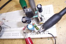
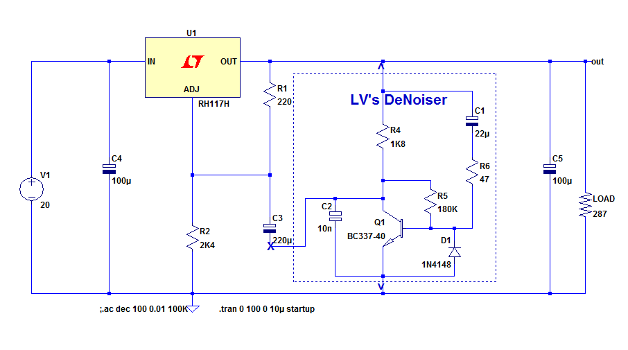
I have made a quick and dirty breadboard test:
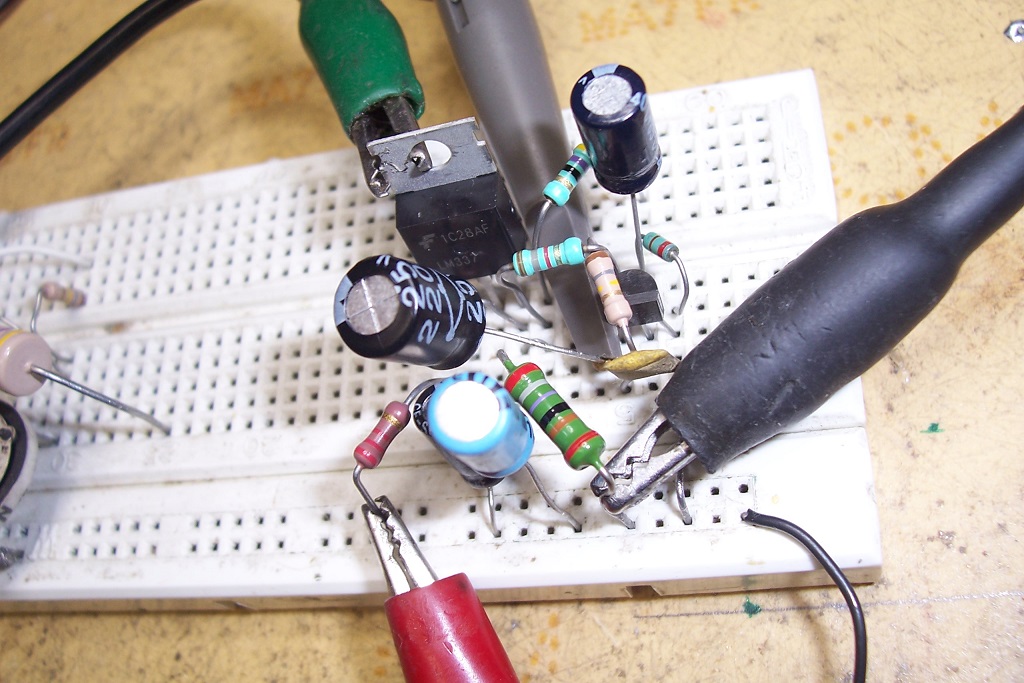
Conclusion: it seems to work exactly like its positive counterpart.
I have explored the effect of the compensation capacitor, and the denoiser is stable for a capacitance >2nF. Of course, you shouldn't use 2n2, but at least twice that value, 3n9 or better 4n7.
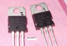
The 337 is a low-cost Fairchild, and as can be seen, it has a thin tab.
I also tried a ST 337, and its behavior was exactly identical.
The circuit was loaded with 287 ohm for an output voltage of 13.5V (~50mA).
I also checked whether a series resistor would improve stability, but the opposite was true: it became unstable with 82 ohm.
As you can see, no effort has been made to minimize parasitic inductances, so this test should be robust enough.
I think that an error has slipped in somewhere: compensation not actually connected or having a wrong value, etc
If you eliminated all possible causes, you can try to increase the compensation cap, up to 22nF (more is possible, but it will impact the HF performance)
Conclusion: it seems to work exactly like its positive counterpart.
I have explored the effect of the compensation capacitor, and the denoiser is stable for a capacitance >2nF. Of course, you shouldn't use 2n2, but at least twice that value, 3n9 or better 4n7.
The 337 is a low-cost Fairchild, and as can be seen, it has a thin tab.
I also tried a ST 337, and its behavior was exactly identical.
The circuit was loaded with 287 ohm for an output voltage of 13.5V (~50mA).
I also checked whether a series resistor would improve stability, but the opposite was true: it became unstable with 82 ohm.
As you can see, no effort has been made to minimize parasitic inductances, so this test should be robust enough.
I think that an error has slipped in somewhere: compensation not actually connected or having a wrong value, etc
If you eliminated all possible causes, you can try to increase the compensation cap, up to 22nF (more is possible, but it will impact the HF performance)
Attachments
Recently I bought two of these kits, which arrived last week.
LM317t LM337t Linear Adjustable Filter Voltage Regulator DC Power Supply DIY Kit | eBay
You had said that it was easy to add the DeNoiser to an existing 317/337 regulator, so I think I will try it with this.
The idea is to regulate the output to +/-30v, and I wonder if the +/-37v input voltage would be enough. What is the drop of these regulators that are not LDO?
Would it be possible to adapt them, with a small piggy back board, of course, for the NoNoiser? Or there might be a high risk of instability?
They look almost like plain-vanilla regs, so the denoiser should work without problem, but there seems to be a cap on Adj, if it is the case you will need to remove it (or recycle it as coupling cap, but I doubt it's a 220µF)Recently I bought two of these kits, which arrived last week.
url=https://www.ebay.com/itm/LM317t-LM337t-Linear-Adjustable-Filter-Voltage-Regulator-DC-Power-Supply-DIY-
You had said that it was easy to add the DeNoiser to an existing 317/337 regulator, so I think I will try it with this.
Normally, the minimal dropout is 2V, they specify 3V perhaps to be safe, or to take into account the rectifier bridgeThe idea is to regulate the output to +/-30v, and I wonder if the +/-37v input voltage would be enough. What is the drop of these regulators that are not LDO?
Yes of course: that's exactly what the denoiser was designed for.Would it be possible to adapt them, with a small piggy back board, of course, for the NoNoiser? Or there might be a high risk of instability?
Don't exaggerate with the wiring length though, and try to twist the three wires together, to avoid picking up ambient 50Hz fields, which are going to be one of the major contributor of the residual noise in the de-noised regulator.
The other likely major contributor is going to be the voltage trimmer: if it can adjust the voltage all the way from 1.5 to 30V, its effect will be huge, and the denoiser will spend most of its efforts trying to remove the crap it introduces.
Better to use a fixed resistor instead
I was lucky to read some good advises on how to deal with the 3X7s and also the LT family 108Xs.
1) Use a larger cap bypassing the output pin than on the output. Say 220uF and 100uF respectively.
2) The output cap shouldn't be a low-ESR type. Or use a small series resistor with the cap.
3) Use diode protection as on datasheet.
4) Some recommend using zener diode on adj pin, but I never learned how to use it.
5) Feed the regulator with an RCR or RLR filtered DC.
6) Some say a large output electrolytic, like 4700uF or more, causes oscillations.
The kits I bought are not assembled, so I can change the parts as I wish. Also makes adapting a piggy-back pcb much easier.
I do not intend to use the trimmer to set the voltage. At most to get to a fixed resistor combo, as was already suggested on the thread.
If I were to use a trimmer it would be a ceramic 1-turn type with a fixed resistor in parallel.
You didn't mention the possibility of adapting the board to use on the NoNoise, probably because of the Kelvin wires. But I think it might be possible to place two of the wires on the piggy board and two on the pcb.
To make a true nonoiser, even with no Kelvin, you would need to butcher your boards to such an extent that starting from scratch, even if it is a perfboard is preferableYou didn't mention the possibility of adapting the board to use on the NoNoise, probably because of the Kelvin wires. But I think it might be possible to place two of the wires on the piggy board and two on the pcb.
To make a true nonoiser, even with no Kelvin, you would need to butcher your boards to such an extent that starting from scratch, even if it is a perfboard is preferable
Point taken. I won't try it.
Thanks for reporting the issue: one can never be sure until a test is actually made.
You say that you didn't detect oscillations, yet all the symptoms seem to indicate just that: the denoiser has no effect on the DC voltage, and if does, that has to be because of parasitic oscillations, there is no other path.
I am going to build a sample on breadboard and investigate. The cure could be as simple as a capacitor value change, or it could not exist
Well , the 10Mhz freq counter on my DVM didn't detect oscillations , but it has limited ability. I don't have an osciloscope to be sure.
That is my guess too : While the LM337 alone works as it should , the combination with the D-N sets off some kind of oscillation. The 1,254 V isn't constant . When I put 1uF over it ( the current setting R with diode) , it is somewhat better but the output voltage increases with around 200mV.
The compensation capacitor is 10nF (ceramic , measured the value , it's a COG ) with the 33 ohm and multi checked that it is connected.
I will check it with 20nF...
I load it with 1k8 , 450, 150 and 47 ohm (ouput 14,60 V) , from 450 ohm = around 32mA , output voltage drops .
Attachments
Last edited:
I tried 10nF more , this time a MKT , and even an extra 22nF (total 42nF) , no change .
But get this :
When soldering the 10nF back out , I also took out a 1uF ceramic output cap to reach the connection of the 10nF/33ohm better. Then testing again and the problem was solved !
Was it the 10nF/33 ohm connection ? No , I checked that a couple of times before . So I desoldered the 1uF from its identical brother without touching the 10nF/33 there ... again this solved the problem !! WTH ? A ceramic cap at the output is the cause of instability ?? Without DeNoiser no problem , but the interaction of those 2 makes it unstable .
This is probably the reason why the LM317 wasn't stable , see post 295 , although that was solved with extra capacitor at the input. LM317 is less picky.
Does this mean no ceramics behind the D-N ? No decoupling of opamps with it ?
Maybe 100nF is tolerated , which is the usual value for decoupling opamp and logic IC's .
Anyway , what a relieve ! After all the work , designing and making (milling) a little PCB and putting the mix of SMD's and TTH components on it , it got me down running into this "little" problem.
Attachments
Last edited:
This has been repeated many times already, but not sufficiently apparently:
About the (simple) LM317/337:
Only one capacitor is required, it is the input cap.
The output cap is not necessary, it is just tolerated. If it is used, it will cause a peak in the output impedance and noise at some frequency, and this peak is proportional to the Q and value of the capacitor: a large, very low esr cap is the worst.
If you decide to use an output cap, the input cap becomes even more essential: you could see it as acting as a counterweight for the weight of the OP cap.
If you use a large, low esr output cap at the output, the input one will need to be even larger and have a lower esr/esL to balance it.
About capacitors in general:
Contrary to an audiophile belief, paralleling large and small caps does not bring the benefits of both: instead it creates various resonances, series and //.
I have made a comprehensive study of the problem, and some excerpts can be found on this forum.
One of the general conclusions was that such a paralleling is always detrimental if C>100*c. This does not imply that lower ratios are beneficial, in fact, the statement is just changed to:
"Paralleling large and small caps is generally detrimental"
When the ratio is lower than 10, the effect can generally be beneficial.
This applies to directly paralleled capacitors; it is generally OK to use a large, low-Q cap on the supply board with a small one at the point of load, further down the wiring.
What does it mean in the context of the Denoiser: the output should use only one cap, normally the large E-cap (100µF in this example), because it has a significant ESR, and the 1µF could be placed at the POL, if it is distant.
The input should have an excellent bypass: a large, low esr E-cap, or a large MLCC, but not both, unless the ratio is <10.
The denoiser will make the 317/337 more demanding regarding these rules.
About the series resistor on the compensation cap: it is never necessary, but it seems to improve the stability for some 317 configurations.
As I mentioned above, this resistor is always detrimental with the 337: 82 ohm is altready sufficient to cause instabilities

Here is my experience.
I have finally made couple of D-noiser boards to make a small workbench supply with regulated output. DN was modified with 2n2955 in parallel for more current. I added simple CCS(BJT,couple of resistor and LED) to output.
I powered it up, connected DMM, and voltage to low then expected, around 20VDC, should have been over 26VDC. Something smells funny. Connected oscilloscope and i saw BIG oscillation if i recall over 1Vpp. Ok, i saw i forgot to add output cap, i added 100uF, oscillation dropped a bit. Then i shorted CE of DN transistor,everything works by the book. So only thing left was to disconnect CCS, what a suprise, oscillation dropped even more but didn't disappeared. So here are my numbers.
With CCS
Regulated voltage range 1,2V-24V, oscillation starts around 13VDC(100mVpp) and rises up to 160mVpp at 24VDC
Without CCS
Regulated voltage range 1,2V-28V, oscillation starts around 20V(40mVpp) and rises up to 80mVpp at 26VDC, after that then drop and around 28V LM317 goes into "clipping"/stops regulating cause low dropout voltage.
With shorted CE everything works fine, regulation goes from 1,2V to 28V without any oscillation.
I still didn't played with vaule of capacitor over CE so i'm hoping there lies the problem.
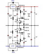
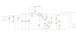
Here is schematic of my DN. Values are a bit "outdated" but i didn't checked this topic frequently so i didn't know about changes in values of some elements. And i forgot to say i didn't had BC337 so i replaced it with BC550 with hfe around 500.
I have finally made couple of D-noiser boards to make a small workbench supply with regulated output. DN was modified with 2n2955 in parallel for more current. I added simple CCS(BJT,couple of resistor and LED) to output.
I powered it up, connected DMM, and voltage to low then expected, around 20VDC, should have been over 26VDC. Something smells funny. Connected oscilloscope and i saw BIG oscillation if i recall over 1Vpp. Ok, i saw i forgot to add output cap, i added 100uF, oscillation dropped a bit. Then i shorted CE of DN transistor,everything works by the book. So only thing left was to disconnect CCS, what a suprise, oscillation dropped even more but didn't disappeared. So here are my numbers.
With CCS
Regulated voltage range 1,2V-24V, oscillation starts around 13VDC(100mVpp) and rises up to 160mVpp at 24VDC
Without CCS
Regulated voltage range 1,2V-28V, oscillation starts around 20V(40mVpp) and rises up to 80mVpp at 26VDC, after that then drop and around 28V LM317 goes into "clipping"/stops regulating cause low dropout voltage.
With shorted CE everything works fine, regulation goes from 1,2V to 28V without any oscillation.
I still didn't played with vaule of capacitor over CE so i'm hoping there lies the problem.
Here is schematic of my DN. Values are a bit "outdated" but i didn't checked this topic frequently so i didn't know about changes in values of some elements. And i forgot to say i didn't had BC337 so i replaced it with BC550 with hfe around 500.
Attachments
A number of remarks: I mentioned here (and elsewhere) that the denoiser should only be used on "regular", non augmented 317 circuits:
D-Noizator: a magic active noise canceller to retrofit & upgrade any 317-based V.Reg.
If it also works with a booster, good for you, but it is at your own risks.
Apparently, you have used a non-tested, theoretically improved version (R5=560 ohm, etc.) of the DN as a base for your build.
It works in sim, but I can only recommend the tested version if you want something that works when the last solder is done.
You can either revert to the normal version, which is going to work (unless the layout is really problematic), because it has been abundantly tested, or try to fix your oscillation problem: since the lower impedance level seems to be the problem, increasing C5 to 33nF or 47nF could solve it (no guarantee).
Note that if you remove your booster, C2 has to be connected directly to the input of the 317 (you can delete C3, which at best will do nothing and at worst increase problems).
To be completely clear, here is the most universal, tested version of the denoiser: it has now been tested on a 337 (reverse all polarities).
I might not be the highest performance one, but it should work on any "normal" (non-modified) 317 or 337 regulator:
Attachments

I will change value of R5 to tested one and see how it goes,then i'll start fiddle with C5. I somehow missed tested version of DN that's why i made one with 560R.
On our local forum we made some serious changes to original DN and works good. I didn't wanted to build that one cause it had too much parts so i decided to build this one. Was hoping gonna be one day project but with work i have it's been like 3 weeks since i made PCBs and soldered all parts.
On our local forum we made some serious changes to original DN and works good. I didn't wanted to build that one cause it had too much parts so i decided to build this one. Was hoping gonna be one day project but with work i have it's been like 3 weeks since i made PCBs and soldered all parts.
You also need to change R6 (in your schematic) to 180K.
In principle, if you use 10nF as a compensation cap and C2 is directly connected to the input, it should work.
Once you have a stable, working base, you can begin to explore other possibilities, incrementally.
It is possible that the boosted version can be made to work: after all, it contravenes the application guidelines of the 317, yet it is given as an example, and it works (most of the times)
Yes I distincly remember you telling us not to use low ESR E-Caps behind the D-N in one (or more) of the 300 posts here , but I didn't think a small 1uF ceramic would matter.
You know I'm a student of the Elektor class , and the big cap's with ceramic bypass C's behind the LM's that they always use is hard to get out of me. If ratio's between cap's larger than 10 deteriorates performance , using even 100 nF bypass C's with a 100uF is bad .
"About the (simple) LM317/337:
Only one capacitor is required, it is the input cap."
Well , the data sheet says 1uF tantalum or 10-25uF E-cap. Again as I showed you before , Elektor uses up to 1000uF , and they are not morons after decades of publishing circuits.
I don't see why a big cap on the output is bad. It's like having a big reservoir of available current ready to deliver at peaks not having to trust on the regulator to keep up. The regulator is just there to keep the reservoir's level steady.
"About the series resistor on the compensation cap: it is never necessary, but it seems to improve the stability for some 317 configurations.
As I mentioned above, this resistor is always detrimental with the 337: 82 ohm is altready sufficient to cause instabilities ".
So you're saying better to leave out the 33 ohm with the LM337+DeNoiser ? I had some 33 in 0805 , so I used them because you said it can't hurt.
It pays to have an oscilloscope to see some small oscillations like Khadgar2007 has.
The DeNoisers now seem stable but who knows what my DVM aren't detecting.
In the context of a bench supply, three more remarks:I will change value of R5 to tested one and see how it goes,then i'll start fiddle with C5. I somehow missed tested version of DN that's why i made one with 560R.
On our local forum we made some serious changes to original DN and works good. I didn't wanted to build that one cause it had too much parts so i decided to build this one. Was hoping gonna be one day project but with work i have it's been like 3 weeks since i made PCBs and soldered all parts.
With an output voltage of 30V, the version with 560 ohm would require a 2W type, so even if you manage to stabilize it, it is probably not advisable.
At very low output voltages, <5V, the denoiser will become less effective, because the correction amplifier will be starved and because the voltage potentiometer will shunt significantly its output.
Such a supply should be protected against all mishaps, including output short, load-dumping, etc
This requires additional diodes to protect the 317 and the transistor:
That sounds like common sense, but the reality is more complicated and less intuitive: a regulator is closed-loop amplifier, and such an amplifier presents an inductive output impedance.I don't see why a big cap on the output is bad. It's like having a big reservoir of available current ready to deliver at peaks not having to trust on the regulator to keep up. The regulator is just there to keep the reservoir's level steady.
If this virtual inductor is associated with a capacitor, it creates a resonance, meaning a severely degraded output impedance and a noise peak.
Audio amplifiers use an inductive Zobel to combat that effect, but on a regulator it is not a realistic option.
If they are DC stable, they are probably oscillation-free: any oscillation tends to shift the DC operation pointThe DeNoisers now seem stable but who knows what my DVM aren't detecting.
Attachments
G'day folks,
Here is my finalised design.


I've got 5 on order from JLCpcb. Their fabbed already and should be picked up by DHL shortly.
Attached is the Gerbers for public consumption.
They could, of course, be easily adapted for other voltages of course by changing R5 and R6.
Here is my finalised design.
I've got 5 on order from JLCpcb. Their fabbed already and should be picked up by DHL shortly.
Attached is the Gerbers for public consumption.
They could, of course, be easily adapted for other voltages of course by changing R5 and R6.
Attachments
You did change the original circuit's DeNoiser add-on.
First tests I have been doing seem to show PSRR is unaffected by input voltage filtering. It doesn't change a bit. Is that so?
Today I tested the LM337 + D-N with only a 100nF ceramic straight at the output, and again the same instability as with the 1uF. Pretty remarkable , it just doesn't want to play ball with a ceramic cap , not even a small one.
If you're like me wanting (wanted) to use the "D-Noizator: a magic active noise canceller to retrofit & upgrade any 317-based V.Reg" , in existing circuits , like preAmps , HPamps based on Elektor designs , you might want to check first for ceramic cap's or even low ESR E-caps at the LM's output. While you think to make it better with the DeNoiser , could be you actually make it far worse , especially with the LM337. So test it before you make changes that are hard to turn back.
Of course , me changing some values of resistors to have a low current version, may have played a role, but my values are about double the Elvee ones and he tested it with values 5 times as high.
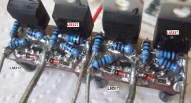
Just finished my 4 DeNoisers today , putting 18V zeners and 1N5819 over the outputs and still works fine (without ceramics) , just with 100uF .
If you're like me wanting (wanted) to use the "D-Noizator: a magic active noise canceller to retrofit & upgrade any 317-based V.Reg" , in existing circuits , like preAmps , HPamps based on Elektor designs , you might want to check first for ceramic cap's or even low ESR E-caps at the LM's output. While you think to make it better with the DeNoiser , could be you actually make it far worse , especially with the LM337. So test it before you make changes that are hard to turn back.
Of course , me changing some values of resistors to have a low current version, may have played a role, but my values are about double the Elvee ones and he tested it with values 5 times as high.
Just finished my 4 DeNoisers today , putting 18V zeners and 1N5819 over the outputs and still works fine (without ceramics) , just with 100uF .
AFAIK it's common knowledge that low-ESR caps are not recommended for the 317 and 337.
Use a 100uF electrolytic non low-esr, as was already recommended by Elvee.
Use a 100uF electrolytic non low-esr, as was already recommended by Elvee.
- Home
- Amplifiers
- Power Supplies
- D-Noizator: a magic active noise canceller to retrofit & upgrade any 317-based VReg