Thank you Pavel, very decent of you........
Have you by chance done any number crunching with the bipolar double emitter follower output stage? It may be possible to extend the operating voltage from 2.4V to say 4.8V end to end by simply placing two series diodes atop the bases of the drivers and a Vbe multiplier between the bases in the conventional way but with the top and bottom of the error correction blocks operating between the anodes of the upper diodes. This also increases the current delivery at each end but I can't see a problem with that.
Cheers,
Hugh
Hugh,
I have not had enough time to do it yet (for error correction amp) and I am doubtful if I have motive to do it ...
Pavel
I have not had enough time to do it yet (for error correction amp) and I am doubtful if I have motive to do it ...
Pavel
David,
I don't think I like this circuit much, although it is certainly clever.
Essentially, when one side of the circuit, say the NPN side, is turning on hard, the upper shunt device turns on, diverting a small portion of the drive current down through the Vbe multiplier to turn on the lower shunt PNP device. This increasing current through the Vbe multiplier increases the voltage across it, and this ensures the driver and output device in the inactive side remains on. The problem is that the turn on mechanism of the lower device is not entirely clear from the schematic - there is much more to it than is suggested here - and any diversion of current from the base of the driver when pressing hard is likely to result in current starvation.
A false dawn, perhaps?
Cheers,
Hugh
AKSA said:[snip]The problem is that the turn on mechanism of the lower device is not entirely clear from the schematic - there is much more to it than is suggested here - and any diversion of current from the base of the driver when pressing hard is likely to result in current starvation.[snip]Hugh
Hugh,
I fully agree with your analysis. But maybe the problem is less than it appears. There are no resistor values in the diagram, but I would expect the diverted current to be on the order of several mA, say 10 mA at the maximum. That would probably not be significant, certainly not in comparison to the large non-linearity that would result from turn off/ turn on. Just my gut feeling.
Jan Didden
Hi, AKSA,
I still don't understand how it works. Do you have simpler words for your explenation? From your previous explenation, which transistor have the starvation of current? I read the post as the inactive side maybe dipping in bias voltage, but not to turnoff state. Is this right?
I still don't understand how it works. Do you have simpler words for your explenation? From your previous explenation, which transistor have the starvation of current? I read the post as the inactive side maybe dipping in bias voltage, but not to turnoff state. Is this right?
David,
The current starvation is from the upper driver base, at a moment when it really needs lots of current - this will have the effect of increasing the source impedance at the base of the upper driver, and could result in compression of the waveform.
Jan,
Thanks for your reply. I'm still a little hazy on how this precisely works; I don't like the current starvation issue for the foregoing reason; truth is, most voltage amps at the base of the drivers operate around 8-12mA, so 10mA would be a big cut at a time when the base of the active device really needs the maximum current drive.
This could be a better arrangement if current sources were supported somehow from each rail.......
Cheers,
Hugh
An explanation of the circuit is given here: http://www.diyaudio.com/forums/showthread.php?postid=282339#post282339
where I "invented" it also. But I wasn't the first. 🙁
Steven
where I "invented" it also. But I wasn't the first. 🙁
Steven
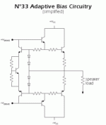
This just came in from DestroyerX. http://www.diyaudio.com/forums/attachment.php?s=&postid=599064&stamp=1111012612
What kind of biasing he is using? Variation from Steven's?
Hi, AKSA,
I got it. I happens because VBE multiplier is a "constant voltage"cct, it can sucks more or less current but gives stable voltage drop.
From the link of Steven's work there is this cct "Tanaka Lapaz". This uses opposite character than VBE multiplier, that is constant current with variable voltage drop. What do you think about this?
Attachments
Lets blow some life to this old but interesting thread 🙂
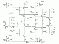
Pavel, I have a plan to design a PCB for your PMA-AB1. The question is weather I should consider to design the R10, R8, R9,R11 resistors as a small multiturn trimmers.
As far as I understand the circuit there might be some very last finetuning possible if these would be trimmers. But if all 4 are trimmers it might be very tricky to adjust them for best performance.
So what are the toughts - would it make sense or not?
Ergo
KP,
Of course...... but that's not to say it's ever been produced, or commercialised.
Brave heart.... it's a clever circuit, although it would be nice if you could jag it with a quiescent of 100mA, no?
Thanks a million for being so generous to Kean, much appreciated from where I stand.
Hugh
Of course...... but that's not to say it's ever been produced, or commercialised.
Brave heart.... it's a clever circuit, although it would be nice if you could jag it with a quiescent of 100mA, no?
Thanks a million for being so generous to Kean, much appreciated from where I stand.
Hugh
This has nothing to do with this thread but you can see some measurement of your Paris headamp in my thread "MPP" under "Analog Line Level"
By the way it sounded much better when i put in a shielded soft steel box.
I also made a small modification by bypassing the Auricap with a 0.1uF Vishay/Röderstein MKP changing the sound a little to my taste. I like some sparkle on top but otherwise i like the sound of the Paris very much. I will also comment on it`s sound in future installments and will comment on the measurments too.
To Pavel : great idea and i will certainly build the circuit when i find the time.
Having worked with Malcolm Hawksford for many years i am very happy that his ideas are now catching up after more then 20 years. I am currently talking to Jan Didden and Malcolm and plan to do some work into error correction too. I think it is one more option to reduce distortion and wothwhile to explore.
error correction amp
Janneman, I have read your articles in AudioXpress and I also enjoyed your interview with Erno Borbley. I have been building his kits and communicating with him over many years.
I am interested in building your error corrrection amp and amp protection scheme that you wrote about in audioXpress from August through December. Are circuit boards available or is there a CB layout already developed?
I checked the AudioXpress web site but I did not see any being advertised.
I do not have a circuit board design software program and are there any you would recommend for design of these boards. I also see that you are active on the DEQX website. I also have their speaker and room correction preamp.
I also have built the Pass Aleph amps and enjoy their sound. Please advise and thanks. How did the wine taste in California? dave
No sense in reinventing the wheel if you have already done this.
Hi Dave,
There is an outfit here in Holland that sells boards (maybe also kits) for my error correction amp: www.pilghamaudio.nl, here:
paX power amplifier
and here:
Amplifier Protection unit
Californian wine is always good to me, but after the European Triode Festival in France a few weeks ago I learned also to appreciate French Champagne 😉
jd
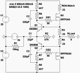
Most probably yes, provided change of resistor values, especially R7. These diodes play interesting role in maintaining thermal stability of the circuit (they are located on PCB, not heatsink).
Anyway - good idea 😉 (again 😉 ), as I have couple of spare PCB's and it is possible to make direct comparison.
A quick glance, maybe if you used a BCV61 and BCV62 dual transistors, you would get thermal matching thus allowing you to drop the diodes with no thermal stability penalty.
Hi PMA,
Would this circuit also work with the IRFP240 / IRFP9240?
I know thermal reactions differ, but did you try it?
Thanks
Would this circuit also work with the IRFP240 / IRFP9240?
I know thermal reactions differ, but did you try it?
Thanks
Hi Tarasque,
it would work, but with modified values of resistors in the correction net.
Regards,
it would work, but with modified values of resistors in the correction net.
Regards,
- Home
- Amplifiers
- Solid State
- New error correction amp