@clsidxxl
Even current LifePO4 power supply can be upgraded to have several 3.3V ultra capacitor/battery hybrid rails.
The reason why ultra capacitor/LifePO4 hybrid power supply is better is that at the back of the ultra capacitor is the pure battery power. While at back of the UCconditioner is the 5V regulator. Even though the UCconditioner still makes big improvement to the 5V RPi rail.
Regards,
Ian
You mean the quality of the supercapacitor charger will influence the quality at the supercapacitor output ?
Good end of weekend Ian.
Good end of weekend Ian.
Thanks again for sharing your designs, Ian!
I think its possible to series connect 3.3v rails (to make 6.6v etc) on the LiFePO4 battery PS, so could you somehow do the same series connection with the Ultracaps installed on each of the 3.3v rails?
I think its possible to series connect 3.3v rails (to make 6.6v etc) on the LiFePO4 battery PS, so could you somehow do the same series connection with the Ultracaps installed on each of the 3.3v rails?
@clsidxxl
Even current LifePO4 power supply can be upgraded to have several 3.3V ultra capacitor/battery hybrid rails.
The reason why ultra capacitor/LifePO4 hybrid power supply is better is that at the back of the ultra capacitor is the pure battery power. While at back of the UCconditioner is the 5V regulator. Even though the UCconditioner still makes big improvement to the 5V RPi rail.
Regards,
Ian
Thanks again for sharing your designs, Ian!
I think its possible to series connect 3.3v rails (to make 6.6v etc) on the LiFePO4 battery PS, so could you somehow do the same series connection with the Ultracaps installed on each of the 3.3v rails?
You can parallel ultra capacitor packages with each LifePO4 cell in the same way to convert any rail into hybrid power supply. Make sure pre-charge each package before you solder them to the board. But please be very careful.
Don't do any series because the on board charger is 3.3V!!!
Ian
Last edited:
Hi Supersurfer
You can try super capacitors with less capacitance but lower ESR. But I can not find any of them so far. I think you have the answer now🙂.
Have a good weekend.
Ian
Understood. The low ESR is important, not capacity.
I will give it a try.
This could be an interesting alternative: PrizmaCap™ - AVX | Mouser Nederland
Small sizes: SCPA20A605PNA AVX | Mouser Nederland
They claim ESR below 1mohm.
The ones you are using have an ESR of 1,9mohm: https://www.maxwell.com/images/documents/2_7_325F_ds_3001962_datasheet.pdf
Regards,
Last edited:
Hello Ian it is possible to make a better draw or photo of the connections?Ultra capacitor/LifePO4 hybrid power supply could be so far the best 3.3V rail in the world. I found a very easy solution to upgrade my LifePO4 power supply board in this way.
3.3V LifePO4 battery power is already very good for low noise clock and DAC applications. However, ultra capacitor /LifePO4 hybrid power supply has even lower internal ESR. So with the upgrade, both response performance and low noise performance can be improved even more. There could be no any other power supply solution can be better than this.
I’ve tried using this upgraded hybrid 3.3V rails for the FifoPi clean side and VCCA of ESS DACs with good result. The improvement of sound quality can be heard clearly during the listening test. I’m very happy with it.
If you had my LifePO4 power supply, I would ask you doing this upgrade today not tomorrow. It will give you a big surprise.
To do so, you will need only 3 or 2 steps,
STEP1:
Prepare a pair of ultra capacitors. You can use either BCAP0350 E270 T13 or BCAP0325 P270 S17.
The second one has lower ESR almost as half as the first one. Connect a 470ohm passive balance resistor in parallel with each cell and then connect the two capacitors together in series.
Also prepare two pieces of wires, AWG18 or bigger.
If you don’t have other way to pre-charge your ultra capacitor package, you will also need a power resistor around 3 ohms.
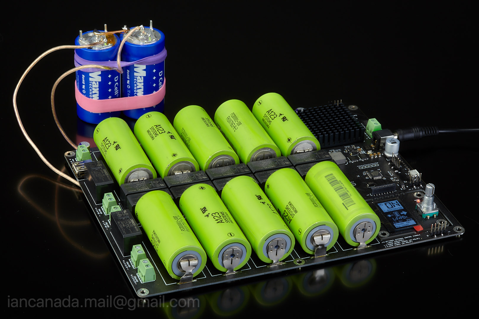
UltraCapacitorLifePO4HybridPowersupply1 by Ian, on Flickr
STEP2:
Solder a wire between the negative of the battery cell of the LifePO4 power supply to the negative of the ultra capacitor package, and a wire from the positive of LifePO4 battery cell to the positive of the ultra capacitor through the power resistor (Or, you can solder them directly to the taps if you use battery holders). Leave them for a couple of hours until the capacitor package is pre-charged to higher than 3.0 volt.
BT6 is corresponding to 3.3V rail on J1
BT7 is corresponding to 3.3V rail on J2
If you can pre-charge the ultra capacitor package to around 3.3V in other way, you can escape this step.
CAUTION: Make sure no any short circuit happens during assembling and soldering. It will be very dangerous because huge energy stored in battery cells even without a DC power connected.
UltraCapacitorLifePO4HybridPowersupply2 by Ian, on Flickr
STEP3:
Remove the power resistor. Make sure both positive and negative terminals of the ultra capacitor package are connected very well to the battery cell.
Now you are having the upgraded hybrid power supply. It’s really not difficult. You no longer need to disconnect or to pre-charge the ultra capacitor package any more as long as you have battery cells installed. You are done!
Re-connect the upgraded hybrid power supply back to your system as before, enjoy the music!
UltraCapacitorLifePO4HybridPowersupply3 by Ian, on Flickr
I would suggest to upgrade the 3.3V rail for the FifpPi clean side first, and then the3.3V rail for the ESS DAC.
Have a good weekend.
Ian


Another doubt is the +-13v rails... it is possible to do the same thing?? Same upgrade? I m asking because i m using +-13v to power an output stage..
Tks
Understood. The low ESR is important, not capacity.
I will give it a try.
This could be an interesting alternative: PrizmaCap™ - AVX | Mouser Nederland
Small sizes: SCPA20A605PNA AVX | Mouser Nederland
They claim ESR below 1mohm.
The ones you are using have an ESR of 1,9mohm: https://www.maxwell.com/images/documents/2_7_325F_ds_3001962_datasheet.pdf
Regards,
I was curious and checked the avx scp datasheet.
I see an dc esr of 39 milliohm for the 11F device (lowest they have)
PN SCPA32A116PNA
20A part is worse, double that number.
Supersurfer ESR is rather 3,2 mOhms on the model that Ian used
BCAP0350 E270 T11 Maxwell Technologies | Mouser France
@ pistollero
the tension is 2,7V by UC,so 2 in series the max is 5V.
BCAP0350 E270 T11 Maxwell Technologies | Mouser France
@ pistollero
the tension is 2,7V by UC,so 2 in series the max is 5V.
Ok.. and with 5 in series you get 13.5vSupersurfer ESR is rather 3,2 mOhms on the model that Ian used
BCAP0350 E270 T11 Maxwell Technologies | Mouser France
@ pistollero
the tension is 2,7V by UC,so 2 in series the max is 5V.
Hmm. Does the voltage distribute evenly across series connected ultracaps? This is generally not the situation with standard electrolytics which require equalising resistors.
I'm confused by Ian's post 764 where he says not to series 3.3v batteries with caps paralleled. From one of G Stew's posts, the battery board relays parallel all batteries when in charge mode so paralleled caps would be charged at 3.3v. When in power mode, the batteries will power as each rail has been arranged at the output connections whether paralleled, in series or a combination of each. How am I figuring this wrong?
Martin.
Martin.
Actually I suspect it charges all cells via individual charging circuits, so that if a higher-current draw from a connected device has drained the connected cell or cells deeper than others connected to other devices, charging the deeper-discharged cells to the target end-charge voltage won't overcharge the other cells on the board.
Ian, can you clarify?
Greg in Mississippi
Ian, can you clarify?
Greg in Mississippi
Last edited:
I was curious and checked the avx scp datasheet.
I see an dc esr of 39 milliohm for the 11F device (lowest they have)
PN SCPA32A116PNA
20A part is worse, double that number.
You are right, I saw the general spec stating: Low ESR: <1mΩ. That’s probably only on big caps.
It seems the only way to get low esr is big caps.
If I had chance to update my LifePO4 power supply design down the road, I will make it compatible with a ultra capacitor board to make things easier to upgrade to a hybrid power supply.
Regards,
Ian
Ian an ultra capacitor extending board which is added to the LifePO4 power supply,is a great idea.
Last edited:
Why not do a lifepo board for transformer output stage only, smaller board, fewer batteries, offsets cost of supercap board and saves some space?
Ultra capacitor/LifePO4 hybrid power supply could be so far the best 3.3V rail in the world. ....
It will give you a big surprise.
Ian
Tried the ultra cap upgrade this weekend and it did give me a big surprise.
More natural easeful sound and extended dynamics, feel much closer to the music.
I’m powering an SD card player and I2s to HDMI module both on 3.3v. Superb result. Best my system has sounded. Thanks very much Ian!
Do you use some on/off switch or relay after the ultra cap, so it does not discharge if you turn of you stereo for a few days. Any recommendations?
Do you use some on/off switch or relay after the ultra cap, so it does not discharge if you turn of you stereo for a few days. Any recommendations?
The capacitor is always connected with the battery, as long as you do not drain the battery it wil stay charged when in isolated (off) state; the battery module is isolated with a relais.
This makes me wonder how much leakage the capacitors will have and if they are able to drain the lifepo4 battery when the battery module is switched off for a longer period of time (like for instance when you are away on summer holiday for 3 weeks).
Regards,
If an ultracapacitor is used, why not leave the 3 ohms resistance between it and the batteries?
Indeed, we keep the benefit of supplying the electronic circuit with the ultracapacitor, we secure the assembly and we keep the benefit of batteries PSU.
The voltage drop in the resistance is negligible for small consumption of digital circuits.
nounouchet
Indeed, we keep the benefit of supplying the electronic circuit with the ultracapacitor, we secure the assembly and we keep the benefit of batteries PSU.
The voltage drop in the resistance is negligible for small consumption of digital circuits.
nounouchet
If an ultracapacitor is used, why not leave the 3 ohms resistance between it and the batteries?
Indeed, we keep the benefit of supplying the electronic circuit with the ultracapacitor, we secure the assembly and we keep the benefit of batteries PSU.
The voltage drop in the resistance is negligible for small consumption of digital circuits.
nounouchet
I think a big reason why ultracaps and lifepo4 batteries do well is their very low output impedance. Adding 3 ohms negates the low output.
Randy
- Home
- Amplifiers
- Power Supplies
- Develop ultra capacitor power supply and LiFePO4 battery power supply