I remember this topic has been up before…..long time ago…..and the conclusion was that there is no practical difference.
Thank you for the quick reply.
Given that it is said to be difficult to tell a 5 watt amp from a 10 watt or a 10 watt from a 20 watt offering, the small increase in clean output power available due to setting the midpoint exactly for symmetric clipping is (as has been said in the posts above) going to make no audible difference... but its still nice to have it set optimally 😉
So what is the "optimal" setting? I think I understand that you guys are saying from 12 to 12.5 volts makes a difference, but 12.5 to 13.0 volts doesn't? Is that right?
Thanks!
Thanks!
If you have a scope, the optimal can be determined by measuring the output
and adjust for symmetric clipping.
Without a scope, you can try the procedure Mooly outlined in post #8106:
https://www.diyaudio.com/forums/pass-labs/215392-amp-camp-amp-aca-811.html#post5976688
Cheers,
Dennis
and adjust for symmetric clipping.
Without a scope, you can try the procedure Mooly outlined in post #8106:
https://www.diyaudio.com/forums/pass-labs/215392-amp-camp-amp-aca-811.html#post5976688
Cheers,
Dennis
Sorry, I don't mean to de-minimize this, but I don't have any of the items that mooly says is needed nor do I want to buy any.
If you had to choose based on just the VOM rating:
12 or 12.5 volts?
If you had to choose based on just the VOM rating:
12 or 12.5 volts?
Sorry, I don't mean to de-minimize this, but I don't have any of the items that mooly says is needed nor do I want to buy any.
If you had to choose based on just the VOM rating:
12 or 12.5 volts?
I think it's fair to say, the higher the voltage the warmer you'll run. If you've got the heat sinking, then running warm is not a major issue. If your heat sinks are small or the amp has to deal with a warm climate, then that constraint will dominate.
If you're not limited by temperature, let your ears decide.
The mid-point DC level needs to be set for symmetrical clipping:
- no oscilloscope -> Follow instructions in #8106 (Mooly)
- oscilloscope available -> Follow instructions in #8112 (Dennis)
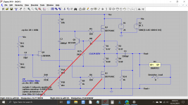
In general, the MOSFET output characteristics is defined by load line, quiescent current, and Vds. In ACA case, the only thing that needs to be done is to set the Vds for a minimal unsymmetric clipping, i.e. both halves of the signal should start clipping at the same time.
The quiescent current is set by Q3.
- no oscilloscope -> Follow instructions in #8106 (Mooly)
- oscilloscope available -> Follow instructions in #8112 (Dennis)
In general, the MOSFET output characteristics is defined by load line, quiescent current, and Vds. In ACA case, the only thing that needs to be done is to set the Vds for a minimal unsymmetric clipping, i.e. both halves of the signal should start clipping at the same time.
The quiescent current is set by Q3.
Many posts say to set the bias at 12.5 while the build guide says 12.
Is there any significant difference?
Edit: Mooly posted above while I was typing this post. It's a very practical way to set bias. Would the change of bias from 12 to 12.5 (or where ever it ends up landing) be audible when the amp wasn't being driven near clipping?
Measurements done on the first version of the ACA with a 19V rail are posted in post 576 of this thread.
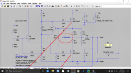
Here is the sim under 3 different bias conditions. Power output in each case is 6.9 wrms, 4 wrms and 4.8 wrms respectively. 24 volt rail assumed in all three cases. The output was reduced slightly from clipping in order to get the undistorted output level.
Attachments
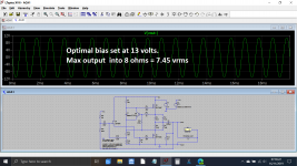
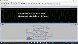
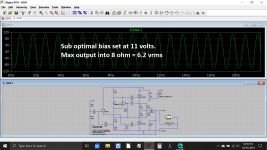
Here is the sim under 3 different bias conditions. Power output in each case is 6.9 wrms, 4 wrms and 4.8 wrms respectively. 24 volt rail assumed in all three cases. The output was reduced slightly from clipping in order to get the undistorted output level.
Was this done with the standard MeanWell 24 V 5 A unit?
It is a simulation but would equate well to the Meanwell PSU in that the supply is a clean and constant 24 volt DC.
Sorry, I don't mean to de-minimize this, but I don't have any of the items that mooly says is needed nor do I want to buy any.
If you had to choose based on just the VOM rating:
12 or 12.5 volts?
I think it's fair to say, the higher the voltage the warmer you'll run. If you've got the heat sinking, then running warm is not a major issue. If your heat sinks are small or the amp has to deal with a warm climate, then that constraint will dominate.
If you're not limited by temperature, let your ears decide.
It doesn't quite work like that 🙂
Look at the total combined dissipation for the two output transistors in these two examples of differing 'bias' settings and you will see that when added together the results are similar, despite the second example have a big difference between the individual dissipation of the two devices.
The first image shows optimal midpoint voltage and the second is way out at almost 18 volts.
(the reason the numbers don't agree exactly is because the ACA does not its quiescent current constant in the face of altering the midpoint voltage, if it did then the results would be identical)
Attachments
Measurements done on the first version of the ACA with a 19V rail are posted in post 576 of this thread.
That post really explains a lot. Thanks for pointing to it.
It doesn't quite work like that 🙂
Look at the total combined dissipation for the two output transistors in these two examples of differing 'bias' settings and you will see that when added together the results are similar, despite the second example have a big difference between the individual dissipation of the two devices.
The first image shows optimal midpoint voltage and the second is way out at almost 18 volts.
(the reason the numbers don't agree exactly is because the ACA does not its quiescent current constant in the face of altering the midpoint voltage, if it did then the results would be identical)
Nice. Thanks.
It makes very little difference where you set it. I tested from 10 volts all the way up to 16 volts and difference is very small. See: Pass ACA Class A Power Amplifier Review | Page 17 | Audio Science Review (ASR) ForumSo what is the "optimal" setting? I think I understand that you guys are saying from 12 to 12.5 volts makes a difference, but 12.5 to 13.0 volts doesn't? Is that right?
Thanks!
It makes very little difference where you set it. I tested from 10 volts all the way up to 16 volts and difference is very small. See: Pass ACA Class A Power Amplifier Review | Page 17 | Audio Science Review (ASR) Forum
I'm sorry that I have to say this, but I find it hard to believe anything coming from you after reading your slanted and biased "review" of the ACA.
My experience with the ACA, and I'm pretty sure everybody else's, is the complete opposite of your "findings".
The above measurements were taken at only 1W.
But, if you leave the midpoint set at, let's say 16V, then the unsymmetrical clipping will start at lower power outputs, which is NOT what you want.
So, in general...
the optimal setting is the setting that gives you symmetrical clipping when ACA is pushed to its maximum power.
But, if you leave the midpoint set at, let's say 16V, then the unsymmetrical clipping will start at lower power outputs, which is NOT what you want.
So, in general...
the optimal setting is the setting that gives you symmetrical clipping when ACA is pushed to its maximum power.
It makes very little difference where you set it. I tested from 10 volts all the way up to 16 volts and difference is very small. See: Pass ACA Class A Power Amplifier Review | Page 17 | Audio Science Review (ASR) Forum
It doesn’t make a difference?
Grab the chairs popcorn and soda sit down and watch a standup comedian. 😂🤣
He measured the influence of mid-point setting, at only 1W power, to see if that would affect the amount of THD. I don't see any problem with that...
It makes very little difference where you set it. I tested from 10 volts all the way up to 16 volts and difference is very small. See: Pass ACA Class A Power Amplifier Review | Page 17 | Audio Science Review (ASR) Forum
You'd be the last person I would take advice from...
- Home
- Amplifiers
- Pass Labs
- Amp Camp Amp - ACA