The Real Test, Can We Drive a COAX Cable?
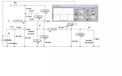
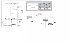
The stand alone ccts shewed little difference running sine waves with no real load connected. For this series I've assumed a real load, 30 feet of COAX, 30 Pf per foot. So the amp needs to drive 900 pF as well as the 100K at the other end. The various switches A, Z & X control what is connected. Or not.
These are all run without the PFB connected.🙂
This time the drive is a square wave running a 20 KHz. The scope is set for single shot, externally triggered direct from the square wave generator.
In each case the positive going transition looks OK. But the negative going trace takes a long time to get back down. This a fundamental property of a CF. The CF, whether triode, pentode or some SS version easily delivers enough charge to drive the capacitive load in a +ve direction. But the charge must then be removed by Rk, the cathode resistor. To do that quickly Rk must be small as practical.
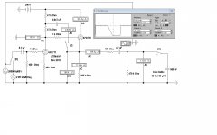
That is not easy for a high mu triode like a 12AX7, the value of Rk in this casebmust be reduced, a lot. So with an Rk of 10K, the waveform looks much better. The 12AX7 would not work well with Rk so low a value.
All that is why a dissimlar triode can be used to advantage in this cct. The other way out is the White CF.😀
Here Endith The Lesson!😱
The stand alone ccts shewed little difference running sine waves with no real load connected. For this series I've assumed a real load, 30 feet of COAX, 30 Pf per foot. So the amp needs to drive 900 pF as well as the 100K at the other end. The various switches A, Z & X control what is connected. Or not.
These are all run without the PFB connected.🙂
This time the drive is a square wave running a 20 KHz. The scope is set for single shot, externally triggered direct from the square wave generator.
In each case the positive going transition looks OK. But the negative going trace takes a long time to get back down. This a fundamental property of a CF. The CF, whether triode, pentode or some SS version easily delivers enough charge to drive the capacitive load in a +ve direction. But the charge must then be removed by Rk, the cathode resistor. To do that quickly Rk must be small as practical.
That is not easy for a high mu triode like a 12AX7, the value of Rk in this casebmust be reduced, a lot. So with an Rk of 10K, the waveform looks much better. The 12AX7 would not work well with Rk so low a value.
All that is why a dissimlar triode can be used to advantage in this cct. The other way out is the White CF.😀
Here Endith The Lesson!😱
Attachments

COAX Cable, Why 50 Ohms (Or 75 Ohms)
When I went with Rohde & Schwarz Sales in 1984 there were still some products that could be bought that used the 60 Ohm standard common in Europe. I had always used 50R while interning in a research lab, much very fast pulse work. All this while Cable, TV & Broadcast were using 75R. So why all the different standards?😕
The short one page note from Bird Electronics of Cleveland covers the subject as best as possible. This note was doing the rounds 10-12 years ago. A very good read!🙂There was quite a bit of learned response, not posted here.
The other note is something I put together for the local club of Antique Radio Collectors. Get out your pocket calculators, all the numbers line up with the common values of the Rs & Cs we use all the time!😱
And if you don't care, just move on.😀
Attachments
I have tried it with different tube CV181Z and there is no hum issue. There seems slight noise as i guess the tube is fairly new.
I think I have to change the input to pin no 4 instead of 1.
Or do I need to try adding some grid resistor in series at the input as usually observed in the mosfets where we use gate resistors to stop oscillations or for stability.
The observed freq is about 50Hz so its not a ground loop.
I think I have to change the input to pin no 4 instead of 1.
Or do I need to try adding some grid resistor in series at the input as usually observed in the mosfets where we use gate resistors to stop oscillations or for stability.
The observed freq is about 50Hz so its not a ground loop.
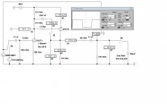
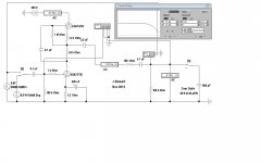
6SN7 Mu Follower for Comparison
This one does well, only 3 db down at 80 KHz driving the 30 feet of COAX. Positive & negative transitions on the square wave look about equal.
So sounds OK & no smoke, gotta be OK.
Did one something like this about 20 years ago.
For curiosity I'll look for the D% results.
Somewhere at the bottom of the pile!!🙂
Attachments
I think I have missed at 1K at the input grid and see if the hum stops. Would there be a chance?
"because I said so, that's why"
So you don't like it, and have no cited testing or even anecdotal info to support a statement that can be easily proven wrong?
What the heck man?
The statement is founded upon established theorethical knowledge. The mu stage is a balanced amplifier having the disagreeable characteristics of balanced amplifiers. No further proof is necessary.
You may be able to create a psudo differential input. Basically if you split the input cathode resistor into two series with a new 15R resistor to ground. If you have big cap there that goes across the top resistor. You then wire the input cable screen to the junction of the two resistors rather than ground. The idea is that then the differential signal between the screen and the input appears across the cathode and grid while the 15R prevents ground current flowing down the input cable.
The other option is to isolate the amp ground from the mains ground with say a 10R.
The other option is to isolate the amp ground from the mains ground with say a 10R.
If I've read you correctly it seems the trouble was a valve with a possible HK short. If this is the case why add a grid stopper? Grid stopper's can effect bandwidth, your effectively adding an RC filter, EG the grid stopper and inter-electrode capacitance.
If you do add a grid stopper, keep it small, 220r - 470r at most. The R should be as near to the valve base pin AFAP, no long resistor lead which adds inductance.
What is the hum now at the OP with the good valve in?
Andy.
If you do add a grid stopper, keep it small, 220r - 470r at most. The R should be as near to the valve base pin AFAP, no long resistor lead which adds inductance.
What is the hum now at the OP with the good valve in?
Andy.
Today I have tried
https://www.diyaudio.com/forums/att...1255-6sn7-mu-follower-cathode-follower-mu-png
increasing the R4 to 5.5K and found that there is no hum now. Everything is stable without any elevated heater rails and no heater regulator or B+ regulator. Right now the input is at pin 1. So do you recommend me to use pin4 as input in the upcoming new pcb?
"there is no hum now." Brilliant, well done.
"do you recommend me to use pin4 as input in the upcoming new pcb" If you can do so without any hassle I would. Pin 4 on an octal base is about an inch (25mm) from pins 7&8 - the heater pins which is far better than the 1/4", 5mm ish, from pin one. It's a better option by far.
Andy.
"do you recommend me to use pin4 as input in the upcoming new pcb" If you can do so without any hassle I would. Pin 4 on an octal base is about an inch (25mm) from pins 7&8 - the heater pins which is far better than the 1/4", 5mm ish, from pin one. It's a better option by far.
Andy.
The statement is founded upon established theorethical knowledge. The mu stage is a balanced amplifier having the disagreeable characteristics of balanced amplifiers. No further proof is necessary.
This is a stunning lack of argument. What disagreeable characteristics? In what way do you see this amplifier as "balanced"?
I think I have missed at 1K at the input grid and see if the hum stops. Would there be a chance?
No, this wont affect hum. It's to prevent parasitic oscillations. Arguably you could get by without it, but it's a little extra insurance that the triode will remain stable. Something from 220R-1000R is plenty.
"there is no hum now." Brilliant, well done.
"do you recommend me to use pin4 as input in the upcoming new pcb" If you can do so without any hassle I would. Pin 4 on an octal base is about an inch (25mm) from pins 7&8 - the heater pins which is far better than the 1/4", 5mm ish, from pin one. It's a better option by far.
Andy.
Cool thank you...!
Finally it seems stable without any oscillations. But I have a question that if we use in a chassis which is magnetically active like mild steel chassis does the tube cannot be near that metallic surface? I see many using copper or aluminum mostly.
I prefer aluminum, as it is less reactive magnetically (but shields better) to transformers, and a bit easier to work with. So long as the tube sockets are mounted securely and the chassis is grounded correctly the tube wont know the difference.
Last edited:
The magnetic flux though a steel chassis is unlikely to affect valves. It can sometimes propagate hum, so be careful to ensure that any signal or AC power cable going though a chassis hole has the return current put through the same hole so there is no net current to induce a magnetic field. Aluminium is lighter and easier to work, but not as strong. Copper is a fashion statement.
Good question. The SRPP could be considered balanced, but not the mu follower. It is decidedly unbalanced. Anyway, what is wrong with balanced circuits? Some people insist on them for audio; some people avoid them. Horses for courses is the best engineering option.Lingwendil said:In what way do you see this amplifier as "balanced"?
I use 2mm sheet ali for my amps and whereas it easier to work in some respects it's also a pain in the ****. It clogs files, drill bits and other tools and it's also harder to join, whereas you can solder or weld steel easily. mind you you can get good strong epoxy's and other glue's that can join ali together.
Also ali isn't as good as a shield as steel but as with anything if you put some thought into layout and placement of tfmr's etc your grand. You can always use copper tape with ali to improve it's shielding, same goes with steel but in your case you should be sound.
Andy.
Also ali isn't as good as a shield as steel but as with anything if you put some thought into layout and placement of tfmr's etc your grand. You can always use copper tape with ali to improve it's shielding, same goes with steel but in your case you should be sound.
Andy.
Lingwendil and others,
Learn. Find the description of the common cathode amplifier in a decent textbook. Don`t add anything to it just to be sure that you are implementing a single ended amplifier. For lowest distortion always use pure amplifying stages and avoid any topological trickeries.
Learn. Find the description of the common cathode amplifier in a decent textbook. Don`t add anything to it just to be sure that you are implementing a single ended amplifier. For lowest distortion always use pure amplifying stages and avoid any topological trickeries.
Last edited:
Incorrect. For lowest distortion, never use active device like tubes on voltage amplifying duty, use transformer instead. Use active device for current gain only. 😀... For lowest distortion always use pure amplifying stages and avoid any topological trickeries.
Lingwendil and others,
Learn. Find the description of the common cathode amplifier in a decent textbook. Don`t add anything to it just to be sure that you are implementing a single ended amplifier. For lowest distortion always use pure amplifying stages and avoid any topological trickeries.
I have "learned" from textbooks, patents, and the indepent testing of others, as well as myself.
From your statement here I take it that you haven't done much in the way of practical research, experimentation and testing. Most of your replies feel like audiophile ad-copy and "philosophy". Being a purist like you are recommending is quite close minded, and I suppose if that's your philosophy in audio then that's fine. Just please don't try to dismiss other ideas and topologies based on your limited understanding. Some of us have gone through the effort of testing and trying many different things, and many authors have as well. Try picking up Morgan Jones' book Designing Valve Amplifiers, 3rd or 4th edition. He gets into fairly advanced testing with some actual measurements and is pretty objective most of the time.
I'm not even a huge user of the mu follower, but it's a great single ended (yes, this is not a blanced, or push-pull type of stage!) circuit for situations where you want to have higher gain and decent drive capability off of a single stage. It also has great PSRR, great overall linearity. A definite drawback in some situations is that it has pretty harsh clipping behavior, but this is not usually a concern if you choose the right tubes and operating points for your given design goal.
The mu follower is basically a common cathode amplifier with a cathode follower acting as a load- the action of the cathode follower "assembly" riding the signal bootstraps it and increased the dynamic load resistance perceived by the lower device, which as you are no doubt aware will greatly increase linearity and gain. There is no "balanced action, and the harmonic content is very similar to a common cathode that is loaded with an equivalently selected load to the reflected resistance shown by the cathode follower and load resistor. Headroom is reduced, but for a linestage this is not an issue in most circumstances.


- Home
- Amplifiers
- Tubes / Valves
- 6SN7 Mu follower or cathode follower?