Balanced circuits, such as the mu stage, produce a more distorted, scattered and meager harmonic spectrum. To my knowledge, there is not any reading material providing a physical basis for my assertions, I had to do my own exploration. The analysis necessitates going beyond classical physics. I also made quite detailed notes, unfortunately, the document has become damaged. Is there any chance of restoring a corrupted rtf file? (I doupt it)
Interesting. Whenever I hear results that don't match up with my experience I like to explore what's different. I would love to see more, but if your notes are gone that's unfortunate. Most of my stuff is on dead laptops or in messy notebooks.

I had to sell off 90% of me test gear and stock of tubes/components a several years ago (cross country relocation that eventually fell through) and haven't been as heavily into audio as I used to be. I really wish I had the time and money to devote back into the way I used to do things.
Last edited:
Balanced circuits, such as the mu stage, produce a more distorted, scattered and meager harmonic spectrum. To my knowledge, there is not any reading material providing a physical basis for my assertions, I had to do my own exploration. The analysis necessitates going beyond classical physics. I also made quite detailed notes, unfortunately, the document has become damaged. Is there any chance of restoring a corrupted rtf file? (I doupt it).
Incomprehensible meaningless ad-copy? Who would use negative words in advertising?
1) Instability is an inherent property of balanced topologies Instability conveys high distortion.
2) Circuit solutions inspired by industrial applications are harmful to the audio signal.
OK?
A fog of BS. I think we are being trolled.😀
The mu follower is associated with high distortion. If distortion matters you should adopt the circuit in post #4.
This is not my experience. Mu followers have very low distortion, very near instrinsic distortion of the tube. Hear are some leads explaining it:
http://www.customtubeconsoles.com/about?tmpl=/system/app/templates/print/&showPrintDialog=1
I haven't red much about gain staging in this line amp. Considering very high signals from CD players and other modern sources, most of times we don't need gain, just drive if at all.
I think so many people are so focused on having a bunch of gear (commercial, or DIY) that they just want to run a pre or linestage with gain. Oftentimes a simple source selector, volume control, and occasionally balance is all that may be necessary. Sometimes a transformer if there is funky ground loops in your setup that can't be helped. In some instances a bit of gain is handy, and I find that something from 3-6x or so works well, and something from 10~15x works well in situations where one is matching mobile devices or running external circuits like a baffle step compensation setup or crossover.
My usual recommendation to folks is to build the 6V6 preamp from Salas' thread. Great way to go for 3-6x if that's what you need, and can drive most any consumer level load/cables. If you need more build a variation of the above circuit with the direct coupled cathode follower.
A cathode follower can help in driving cables or tricky loads, but even then they aren't totally necessary. I have several preamps with gain collecting dust (or that eventually will be given away) simply because my builds have enough gain on their own, and are right near the source and other equipment.
Some Mu Follower Distortion Measurement Results
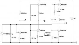
I did this work in 1999 as part of a line follower cct investigation. If we think of it, the top tube in a mu follower forms the load for the bottom tube. What effect does the top tube have on the bottom tubes performance sofar as D% is concerned?
Theory & practice sez the load Rl should be at least 2X rp & preferably 3x or more to reduce distortion. When the top tube in these example is passive, load is only One times rp when both triodes are similarly biased.
So there are three kinds of loads in each series, an ordinary 36.5K load (A), a passive triode biased same as the bottom tube (B) & an active tube on the top (C). Conditions for each test are kept the same, a 300V PS & D% is taken at 10VAC out. The tests were done one after the other, not three triodes all in the cct together as in the schematic. Does all that make sense?
One series tests a 6SN7, the other a 6BL7. The 6BL7 is only marginally better than the 6SN7 in these tests. On the other hand, the 6BL7 can dissipate more watts total, 12 vs 7.5. So for driving low impedance loads where more current is required should do better than the 6SN7.🙂
Attachments
A fog of BS. I think we are being trolled.😀
Yes, "beyond classical physics" (quote) 😀
I did this work in 1999 as part of a line follower cct investigation. If we think of it, the top tube in a mu follower forms the load for the bottom tube. What effect does the top tube have on the bottom tubes performance sofar as D% is concerned?
Theory & practice sez the load Rl should be at least 2X rp & preferably 3x or more to reduce distortion. When the top tube in these example is passive, load is only One times rp when both triodes are similarly biased.
So there are three kinds of loads in each series, an ordinary 36.5K load (A), a passive triode biased same as the bottom tube (B) & an active tube on the top (C). Conditions for each test are kept the same, a 300V PS & D% is taken at 10VAC out. The tests were done one after the other, not three triodes all in the cct together as in the schematic. Does all that make sense?
One series tests a 6SN7, the other a 6BL7. The 6BL7 is only marginally better than the 6SN7 in these tests. On the other hand, the 6BL7 can dissipate more watts total, 12 vs 7.5. So for driving low impedance loads where more current is required should do better than the 6SN7.🙂
I guess you dont need 10V peak output its way too much if the amplifier has got gain of 26db or above. So what is the THD in case of 1V peak?
Ok i got rid of the problem with Mufollower. I hear many say that CF is also good but it has gain of about 10. Im planning to go with the following config. Can anyone recommend me that is there anything in it to change?
If you like the CF but need lower distortion (and a bit more gain) you could bootstrap the first anode resistor.
An interesting question but leads to another. First of all, the output is not 10V peak, it is 10V RMS, so 14V peak. For Class A triodes a rule of thumb is the D% is proportional to the signal level, so at One volt the D% would be 20 db less.I guess you dont need 10V peak output its way too much if the amplifier has got gain of 26db or above. So what is the THD in case of 1V peak?
For the 6SN7 Mu follower vers at 10 V RMS the result is 0.2% of 2nd & much less 3rd. So at One volt would be 0.02%.
The question becomes, 'Can You Hear 0.02% Distortion'. Probably not.
After passing thru your loudspeaker the D% will be orders of magnitude larger, will the Mu Follwer result be audible? To those with bats ears possibly, several who seem to inhabit DIY.
When designing a system all the parts need attention, some much more than others. The loudspeaker system & the listening space are by far the most important. A line stage is a trivial problem. Just needs some common sense applied.😀
Are you designing to maximize cost? The 5AR4 is very expensive now. And far too much rectifier for this very trivial project. Any serious designer would reject that choice.😱I'm planning to use a 5AR4 to power these tubes. Is there any design that you would recommend?
Save the 5AR4 for a power amp.🙂
This thread on CF & Mu Followers has gone on for 10 months with little or no good results even after much learned advice given by others. Now you are looking at a multichannel thing. What next!!
First things first, finish what you have started & shew us some results. All talk & little or no action will never get you to where you say you want to go.
Will you still be talking about the same things 10 months from now with no results?😀
And you still did not answer my question, can you hear 0.02% distortion. If you can many researchers studying hearing would like to test your ears.🙂
And publish a paper on the results!🙂
I think many cannot distinguish < 0.5% distortion. Im not denying that. As per the above adjustments made the tube is working fine like no hum now just thought of solid state rectifier and solidstate regulator but a friend of mine suggested to go with a tube rectifier as it sounds better than ss so thought of going that way but i want it for both 2 channel and multi channel application so that I can buy one tube and use it for both applications.This thread on CF & Mu Followers has gone on for 10 months with little or no good results even after much learned advice given by others. Now you are looking at a multichannel thing. What next!!
First things first, finish what you have started & shew us some results. All talk & little or no action will never get you to where you say you want to go.
Will you still be talking about the same things 10 months from now with no results?😀
And you still did not answer my question, can you hear 0.02% distortion. If you can many researchers studying hearing would like to test your ears.🙂
And publish a paper on the results!🙂
Right now the pre is working fine without hum but the only problem is its gain which is 20. Btw just to check how much value of volume pot to be put in here im thinking of 47k volume pot.
I think many cannot distinguish < 0.5% distortion. Im not denying that. As per the above adjustments made the tube is working fine like no hum now just thought of solid state rectifier and solidstate regulator but a friend of mine suggested to go with a tube rectifier as it sounds better than ss so thought of going that way but i want it for both 2 channel and multi channel application so that I can buy one tube and use it for both applications.
Right now the pre is working fine without hum but the only problem is its gain which is 20. Btw just to check how much value of volume pot to be put in here im thinking of 47k volume pot.
The rectifier in this cct should not 'sound' at all, the load is constant. It will create a hum problem only if it is not properly isolated by a filter. A PI section CLC will do that. A regulator is a waste of time & money. And another potential problem for an amateur. Easy to destroy in a HV cct.
So SS rectifier is a simple & safe choice, unless you want something to look at. 5V4G/GA would work well. A 47K pot is OK for VC.
How did you measure the gain? the 6SN7 has a Mu of 20, so gain in the cct as shewn would be ~15.
I did not use DC on the Mu Follower heater cct posted here yesterday but never had hum problems. That would have appeared in the distortion measurement. I used both an FFT & an HP334 THD Analyzer. The gain of a mu follower approaches mu of the lower tube, so almost 20.
The mu-follower is basically a type of SRPP, so it is push pull under certain conditions. This happens when the load impedance is less than the mu of the upper triode times the resistance that spans the anode (lower) to cathode (upper). It's sort of an academic argument though since the PP current is usually puny compared with the quiescent current in most designs.
There is no reason to be ambiguous. The mu follower is balanced under all conditions regardless of the magnitude of quiescent current and load impedance. Again, it is not possible to consistently describe its properties and mode of operation in terms of impedance only. Shunt regulated push-pull and single ended push-pull are nonsensical names.
This is not my experience. Mu followers have very low distortion, very near instrinsic distortion of the tube. Hear are some leads explaining it:
Very low mathematical distortion maybe, but that has nothing to do with reality. As the gain approaches mu, distortion increases alarmingly.
What in the hell is "intrinsic distortion"?
As the gain approaches mu, distortion increases alarmingly. What in the hell is "intrinsic distortion"?
Actually, gain approaches mu with increasing load impedance, which is the lowest distortion condition for triodes. Intrinsic means innate, and is used to distinguish a characteristic of the device from a characteristic of a particular circuit.
All good fortune,
Chris
There is no reason to be ambiguous. The mu follower is balanced under all conditions regardless of the magnitude of quiescent current and load impedance. Again, it is not possible to consistently describe its properties and mode of operation in terms of impedance only. Shunt regulated push-pull and single ended push-pull are nonsensical names.
Very low mathematical distortion maybe, but that has nothing to do with reality. As the gain approaches mu, distortion increases alarmingly.
What in the hell is "intrinsic distortion"?
Bunk! Shew us some proof with measurement data. Include what equipment was used, under what conditions were the measurements made. With a diagram.
Prove you know what you are talking about. Talk is cheap, action now or roll up your rug.😀
Actually, gain approaches mu with increasing load impedance, which is the lowest distortion condition for triodes. Intrinsic means innate, and is used to distinguish a characteristic of the device from a characteristic of a particular circuit.
No. It is the highest distortion condition for any amplifying device.
Distortion cannot be extrinsic. What does the sentence "Mu followers have very low distortion, very near instrinsic distortion of the tube." imply?
- Home
- Amplifiers
- Tubes / Valves
- 6SN7 Mu follower or cathode follower?