Something that can be tried to help with instability is to use a bias spreader capacitor.
This goes from one gate to another, between the drivers.
Can search for those terms and find some examples, most of which are with lateral fet output designs. That has a better sonic trade off versus the gate to drain on the outputs, imo.
This goes from one gate to another, between the drivers.
Can search for those terms and find some examples, most of which are with lateral fet output designs. That has a better sonic trade off versus the gate to drain on the outputs, imo.
A capacitor directly from one gate to another worsened things, but if you could contribute some link I would appreciate this.
The bias spreader is blocked with 100nF and between the bias spreader and the gate resistors there are bjt emitter follower buffers.
The bias spreader is blocked with 100nF and between the bias spreader and the gate resistors there are bjt emitter follower buffers.
Last edited:
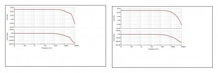
The simulated OLG exhibits 52.7 degree phase margin at fc=3.2MHz.
dont you think that phase margin is low? what about the phase margin from 30KHz to 50KHz .... 15 deg?
I think this is "condititional" stability and might be ok.dont you think that phase margin is low? what about the phase margin from 30KHz to 50KHz .... 15 deg?
But these compensation values are not engraved in stone - feel free to play with the asc file.
5~7MHz oscillations occured when I screwed the module to the heatsink. Fiddling with ground did not show any improvements. So I measured the capacitance between TO-3 case and the alu heat coupler - readout was 300/350pF or 650pF for both MOSFETs. Never did I expect such a big capacitance!
In this case mounting the power module switched an additional load capacitance of 650pF to the output - enough to let it oscillate. This certainly indicates poor stability and so I was investigating again...
To make a long story short I discovered the current mirror between LTP output and VAS input as critical. A 100pF cap connecting the base of Q2 with the neg supply greatly enhances stability. So I assume that the intrinsic Ccb of Q2 formed a pole in the critical region of 5~7Mhz that is bypassed by the base blocking cap. Increasing its value degrades the 1MHz sine output at high levels, 100pF is just fine here.
So it looks like this variant works stable w/o snubber and w/o load.
Last edited:
Area of TO3 about 6cm^2, thickness of typical insulating heatpad 0.2mm, not suprising the capacitance is in the 100's of pF range given the heatpad's likely composition (ZnO perhaps which has dielectric constant of 8.5)
A rough rule of thumb is 1pF per cm^2 for a 1mm spacing, scale for area, 1/separation, dielectric constant.
A rough rule of thumb is 1pF per cm^2 for a 1mm spacing, scale for area, 1/separation, dielectric constant.
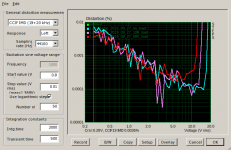
This looks to be IMD , how about the harmonics at 10w . What bias current you ended up with ?Today I add TIM measurements with 5R/10R and no load. I assume that distortion level is hidden within the noise floor, which is dominated by soundcard output noise.
You are right, this is IMD. Bias was all the time 100mA.This looks to be IMD , how about the harmonics at 10w . What bias current you ended up with ?
You can read IMD/10W at the depicted plot at 10V/10R and 7V/5Ohm respectively.
Is there some way to display the harmonics within STEPS?
edit: I see ARTA FFT offers multitone measurements.
Last edited:
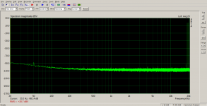
So I measured the spectrum of 2-tone IMD 19/20kHz with ARTA.
10Vrms/20dBV at 10R/no load
7Vrms/17dBV at 5R0 load
What do you think of the result?
10Vrms/20dBV at 10R/no load
7Vrms/17dBV at 5R0 load
What do you think of the result?
Attachments


Thank you for the kind words. It is nice to see knowledge transfer being appreciated. The 2-pole compensation is well known for decades. And has been extended to nested feedback loops by Bruno Putzey, for instance. I followed the general rule to reduce additional poles of the gain stages, making them as fast as possible. And I reduced miller cap as far as I could. Most of the development was fiddling with LTSpice for best theoretical performance. So I do not think that there is some detail in my circuit you have never seen before somewhere. All in all it is a composition of what I call good engineering practice.I love your compensation technique. I definitely adopted it . I applied on beginner's CFA 150W amp . and result you can see before and after . Mille bravo . Is it your invention this two way compensation? Is it baptized?
cheers
Last edited:

How about clarity in sound compare to Class D ?
Some lateral mosfet amp from old days had really poor sound and produce very much heat....
10 years ago have tested sound quality in Audio Setup
1. lateral mosfet amp with Hitachi Devices +/- 80 Rail
running very very hot - sound quality was lowest from all mosfet amps
Cheap Chinese no name bipolar PA amp sound better in mid and high
2. Mosfet Amp with Hexfet IRFP240/IRFP9240 +/- 80 VDC Rail
running hot but not same like lateral amp, sound was better and clearer
3. N Channel Amp Mosfet or IGBT in same circuit +/- 80 VDC Rail
Sound quality was the best, easy audible in Fullrange HI-FI Home Setup or PA Subwoofer and PA Cabinet speakers
Temperature was lowest @ full output power, Lateral amp run hottest
4 Class D PA amplifier from Powersoft
NO WAY for lateral / Hexfet / IGBT amp
Class D amp beat all in clarity and natural sound reproduction
I have discontinued spend time for classic amp design and move to class D
Last edited:
Audio Precision
Could you, please, informe your audio precision model number?
Thank you in advance
Could you, please, informe your audio precision model number?
Thank you in advance
Three plots, only two loads/levels listed. But that's very clean, no difference product visible, 3rd-order product well down.
How about clarity in sound compare to Class D ?
Some lateral mosfet amp from old days had really poor sound and produce very much heat....
10 years ago have tested sound quality in Audio Setup
1. lateral mosfet amp with Hitachi Devices +/- 80 Rail
running very very hot - sound quality was lowest from all mosfet amps
Cheap Chinese no name bipolar PA amp sound better in mid and high
2. Mosfet Amp with Hexfet IRFP240/IRFP9240 +/- 80 VDC Rail
running hot but not same like lateral amp, sound was better and clearer
3. N Channel Amp Mosfet or IGBT in same circuit +/- 80 VDC Rail
Sound quality was the best, easy audible in Fullrange HI-FI Home Setup or PA Subwoofer and PA Cabinet speakers
Temperature was lowest @ full output power, Lateral amp run hottest
4 Class D PA amplifier from Powersoft
NO WAY for lateral / Hexfet / IGBT amp
Class D amp beat all in clarity and natural sound reproduction
I have discontinued spend time for classic amp design and move to class D
Great man, your comment forced to leave tge forum
This is one of the coolest threads I've ever seen at this group. It would be great to know what happened to the project?
Fantastic work, Voltwide / 29285. I really hope that we get an update at some point and I hope that you are out there somewhere (enjoying your amp!).
Fantastic work, Voltwide / 29285. I really hope that we get an update at some point and I hope that you are out there somewhere (enjoying your amp!).
- Home
- Amplifiers
- Solid State
- Just another lateral FET amp