Soldering tips
Hi acowans
Welcome abroad from another newbie!

As far as I can see, you are already pretty much underway.
Until the great folks here implement an extremely comprehensive guide for folks like us, we just have to be careful, cautious, and thorough. Since these are basic requirements for success with building stuff, they may or may not follow up to your request. BUT you can rest assured they really are great, patient and very helpful.
In the meantime, you could start with the infos on the ACA-introduction on diyaudiostore, you‘ll find plenty of information about how to solder, what stuff to use, etc.
Also, have an eye on YouTube, using basic key-words like „soldering beginner“ or something like that. You‘ll find what you need...
Best wishes for many more great projects here at DIYAUDIO...
da
Hi acowans
Welcome abroad from another newbie!
As far as I can see, you are already pretty much underway.
Until the great folks here implement an extremely comprehensive guide for folks like us, we just have to be careful, cautious, and thorough. Since these are basic requirements for success with building stuff, they may or may not follow up to your request. BUT you can rest assured they really are great, patient and very helpful.
In the meantime, you could start with the infos on the ACA-introduction on diyaudiostore, you‘ll find plenty of information about how to solder, what stuff to use, etc.
Also, have an eye on YouTube, using basic key-words like „soldering beginner“ or something like that. You‘ll find what you need...
Best wishes for many more great projects here at DIYAUDIO...
da
I am a newbie at building and started my Pass amp ACA today. I had a hard time confidently figuring out which resistors were which- the color code on the masking tape for each pack was washed out on a few and hard to determine what it was. I do have a multimeter and checked them all but was not confident that I was understanding the schematic when checking it. I also was confused by the photos of the finished boards - the color bands on some of the resistors was really hard ot determine- blue looks black for instance.
It's be super helpful if there were a reference list that simply indicates which resistors go into which board slots- both by value and by color banding- I don't see this anywhere. I do see the list of the included resistors and their value but it'd be most helpful if they were also referenced to their location on the board.
I ended up putting two wrong ones in, soldered, clipped and then had to de-solder them to get them out.
Is there a detailed youtube vid on soldering the resistors in or a cheat sheet the details which resistor goes into "R7", which go into "R9" etc?
Also, should I be soldering from the top of the board or the bottom?
Thanks ! Looking forward to getting this done right and firing it up !
What is the highest voltage rail you can use for ACA? In a chassis with a built in power supply providing 43v DC already, what kind of voltage regulator would be required to get the voltage down to ACA range?
Keep to 24 volts for the kit ACA. (Others have used slightly higher voltages, but have changed components to suit... look to ACA with premium parts?)
So you need to loose 19 volts at 3 amps for a simple stereo ACA, that is 57 watts of heat to dissipate. And the ACAs will give you 72 watts of heat...
Better to find another power supply?
So you need to loose 19 volts at 3 amps for a simple stereo ACA, that is 57 watts of heat to dissipate. And the ACAs will give you 72 watts of heat...
Better to find another power supply?
Yes, I could just attach another power supply to the AC plug from the back of the chassis. I would like to use a linear power supply, and will have to measure the proportions.
JFET Alternatives
A very dear friend who wanted to group build the ACA with students asked me what I would use as substitute for the 2SK170.
The purpose being a low-cost project, the 2SK170 or LSK170 is out-of-proportions expensive.
Normally I would have suggested 2x 2SK209GR in parallel, as mentioned elsewhere before.
But he insisted that for a beginner project SMD would be absolutely no go.
So I had a search in the thread and found the measurements by Preamp :
https://www.diyaudio.com/forums/pass-labs/215392-amp-camp-amp-aca-93.html#post5465132
(Post #4613)
While this is very comprehensive, only the J112 is not NOS and not SMD.
So I took the challenge and tried out a few others in Spice.
Please feel free to play around with those in the Zip file.
Apart from J113 (or J112 which I find Idss too high), a good candidate is PF5102, which is unfortunately also EOL.
But Mouser still has 50,000+ at minimal cost.
Also, as it is "merely" an input follower, it seems that we can make it work with MOSFETs or high-hfe BJTs.
There is not a huge impact on the distortions, but of course they are all likely to sound slightly different.
But for a starter project when cost is more important, it is a small compromise to make.
I am sure Nelson would have his opinion as well.
So, have fun.
Cheers,
Patrick
.
Attachments
For ACA monoblocks I've switched from the Meanwell SMPS to ebayed Chinese Zerozone 24V/5A linear supplies. The improvement is remarkable and well worth the delivered price of $450 for the pair.
...Normally I would have suggested 2x 2SK209GR in parallel...
So, have fun.
Cheers,
Patrick
.
When paralleling this JFETS would you put a little source resistance too?
For better current sharing?
10 Ohm or something in this range
For ACA monoblocks I've switched from the Meanwell SMPS to ebayed Chinese Zerozone 24V/5A linear supplies. The improvement is remarkable and well worth the delivered price of $450 for the pair.
Could this be ok for the normal ACA ?
Zerozone 100VA 19 V Ultra Low Noise LPS Hi-end Linear Power Supply For Audio | eBay
> When paralleling this JFETS would you put a little source resistance too?
> For better current sharing?
I don't, because I match them all to < 10µA.
Patrick
> For better current sharing?
I don't, because I match them all to < 10µA.
Patrick
Trying ACA bridged and paralleled
Hi all
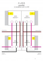
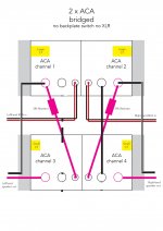
Im getting near to to trying ACA bridged and paralleled. I have made some schematics of what I think are the correct wiring for the two options. one ACA will be mounted on top of the other with a fan between. I want to tie the channels together vertically due to different spec c1 in each stereo ACA, so I have one of each flavour in each channel (I blow one and replaced both sides of one ACA).
Ive arranged the schematics to match the input/output layout I have on the backplate and there are also a couple of photos to show same.
I think I have it right any comment would be very welcome thanks
Hi all
Im getting near to to trying ACA bridged and paralleled. I have made some schematics of what I think are the correct wiring for the two options. one ACA will be mounted on top of the other with a fan between. I want to tie the channels together vertically due to different spec c1 in each stereo ACA, so I have one of each flavour in each channel (I blow one and replaced both sides of one ACA).
Ive arranged the schematics to match the input/output layout I have on the backplate and there are also a couple of photos to show same.
I think I have it right any comment would be very welcome thanks
Attachments
... Ive arranged the schematics to match the input/output layout I have on the backplate and there are also a couple of photos to show same.
I think I have it right any comment would be very welcome thanks
Sorry but neither is correct.
'RCA Bridge' mode:
If you use the ACA build guide as reference, the Red outputs are joined and are actually the -ve or GND line. The Black outputs are the independent outputs. It looks like you have swapped these round in your schematic. That does not matter if you remember the 'RCA Bridge' mode uses the two independent outputs. The two Black terminals in the Build guide or the two Red terminals as you have drawn them. The common -ve / GND (black as you have drawn it) is not used.
'Parallel' mode:
Assuming you have swapped the red and black terminals round (as above) then you should add a link between the two black output terminals as well. Otherwise you will be using the power supply and input cable returns as the link...
I assume the Large C / Small C is to drive two units per speaker? That will only work if you have 4 amplifiers. When you mono block the ACAs you will have just two...
Hi thanks for the repley
the small c and Big c represent the reason for splitting vertically rather than doing the same on each amp, they represent c1 capacitors being the difference between the two stereo amps.
the speaker outputs + and - are swopped round from the ace build guide my. + red speaker terminals are on the outside.
So I think Im right in saying all I have to do is link the black - ve outputs as you say. I had assumed that's they only needed to be linked at imputes but will add that's link.
Attachments
Last edited:
OK lets get a couple of things confirmed before we go any further.
First, Which output terminals on your builds go to the GND (0v) line? Red or Black?
Second, what does Large C and Small C mean? Physical size or capacity or..?
IMHO horizontal would be better, neater and easier than the vertical build idea. What power supply(ies) are you intending to use?
The parallel picture is fine as it stands.
The Bridged mode depends on the answer to the first question.
Attachments
OK lets get a couple of things confirmed before we go any further.
First, Which output terminals on your builds go to the GND (0v) line? Red or Black?
Second, what does Large C and Small C mean? Physical size or capacity or..?
IMHO horizontal would be better, neater and easier than the vertical build idea. What power supply(ies) are you intending to use?
The parallel picture is fine as it stands.
The Bridged mode depends on the answer to the first question.
black 0v neg -
red v positive +
both caps are the same capacity and voltage as per ACA BOM so as they are different I need to split so one of each on each bridged channel otherwise it will make me uneasy!
Thanks
black 0v neg -
red v positive +
both caps are the same capacity and voltage as per ACA BOM so as they are different I need to split so one of each on each bridged channel otherwise it will make me uneasy!
Thanks
If you are sure the Black terminals are connected to the GND / 0 volt line then they will all be connected together through the power supply leads, so no output...
So the 'Parallel v2' scheme cannot work.
V3 is what you would need to do. I have left a wire between 2 of the black terminals to bond the 0 v / GND of both ACAs together.
If you are using two power supplies, then it will be much better to go 'horizontal' (however you want to configure your caps...) then each monoblock will have its own power supply rather than 'share' half and half with the other block.
Attachments
If you are sure the Black terminals are connected to the GND / 0 volt line then they will all be connected together through the power supply leads, so no output...
So the 'Parallel v2' scheme cannot work.
V3 is what you would need to do. I have left a wire between 2 of the black terminals to bond the 0 v / GND of both ACAs together.
If you are using two power supplies, then it will be much better to go 'horizontal' (however you want to configure your caps...) then each monoblock will have its own power supply rather than 'share' half and half with the other block.
there are two DC 24V 8A 200W switching power supplies one power supply per finished channel lh top 1 and lh bottom 3 share a power supply as does the righthand side 2 and 4 each combined channel will share gnd and /o volt.
Last edited:
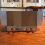
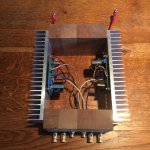
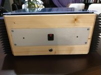
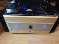
My ACA ready for speakers or headphones.
For the cabinet I used recycled material that I had in my workshop, including big heatsinks.
I am using B+19vdc. I don´t rule out changing to B+24vdc in the future but for the moment I am satisfied with the performance. 🙄
For the cabinet I used recycled material that I had in my workshop, including big heatsinks.
I am using B+19vdc. I don´t rule out changing to B+24vdc in the future but for the moment I am satisfied with the performance. 🙄
Attachments

I think it's a good option (and economical) if you use planar headphones like Audeze, Mrspeakers.... With the HD800 I am enjoying a lot.
With more sensitive headphones type Grade, Fostex ... sounds great but I think it is more prone to noises.
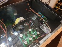
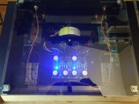
As for the construction, what has given me the most problems is the arrangement of the transformer. I had to spend a lot of time moving it until I found a place/position where no noise induced.
As its use is going to be almost exclusively for headphones, I am thinking of switching to B + 24vdc. 😕
With more sensitive headphones type Grade, Fostex ... sounds great but I think it is more prone to noises.
As for the construction, what has given me the most problems is the arrangement of the transformer. I had to spend a lot of time moving it until I found a place/position where no noise induced.
As its use is going to be almost exclusively for headphones, I am thinking of switching to B + 24vdc. 😕
- Home
- Amplifiers
- Pass Labs
- Amp Camp Amp - ACA