Hi,
I've been thinking on building a class AB amp for my Full range speakers with the following criterion:
1) No global feedback. Apparently High efficiency full range speakers tend to dislike global feedback. probably because it results in a much higher damping factor.
2) High quiescent current for low power class A operation.
3) Low power (5 to 10W) is probably enough.
4 ) Reasonable distortion levels (< 0.2%)
5) Fixed supply voltage.
6) Minimum number of stages.
7) Single supply operation as I intend to power it from a power brick.
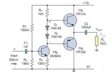
Of course the easiest starting point would be the traditional 3 transistor with 2 diode for biasing as in the attachment. To push the circuit deeper into class A territory I will use 3 diodes and additional resistor resistor at the emitter.
However a quick analysis will show it is not a very viable circuit.
1) The driver will not have enough current to drive the output transistor at high voltage swings.
There are many ways it can be solved:
1) darlington TIP120 for the output transistors
2) Sziklai Pair
3) or a beefier driver stage with higher bias current by using smaller value resistors. However that will result in very low input impedance, so might have to use a mosfet or Jfet to drive the transistors.
4) Use a voltage follower for the driver stage and an additional gain stage.
I would like you opinion which do you think is the best solution.
Other than that would appreciate any comments of how this can circuit can be improved?
1) Zener regulator for the driver stage?
2) resistor and large cap power supply bypass for the driver stage?
Thanking all in advance.
Oon
I've been thinking on building a class AB amp for my Full range speakers with the following criterion:
1) No global feedback. Apparently High efficiency full range speakers tend to dislike global feedback. probably because it results in a much higher damping factor.
2) High quiescent current for low power class A operation.
3) Low power (5 to 10W) is probably enough.
4 ) Reasonable distortion levels (< 0.2%)
5) Fixed supply voltage.
6) Minimum number of stages.
7) Single supply operation as I intend to power it from a power brick.
Of course the easiest starting point would be the traditional 3 transistor with 2 diode for biasing as in the attachment. To push the circuit deeper into class A territory I will use 3 diodes and additional resistor resistor at the emitter.
However a quick analysis will show it is not a very viable circuit.
1) The driver will not have enough current to drive the output transistor at high voltage swings.
There are many ways it can be solved:
1) darlington TIP120 for the output transistors
2) Sziklai Pair
3) or a beefier driver stage with higher bias current by using smaller value resistors. However that will result in very low input impedance, so might have to use a mosfet or Jfet to drive the transistors.
4) Use a voltage follower for the driver stage and an additional gain stage.
I would like you opinion which do you think is the best solution.
Other than that would appreciate any comments of how this can circuit can be improved?
1) Zener regulator for the driver stage?
2) resistor and large cap power supply bypass for the driver stage?
Thanking all in advance.
Oon
Attachments
You try first a series resistor with your speaker driven with a standard amplifier to determine the required damping factor. The circuit you show has a relatively low output impedance, but adding a bootstrap you get near zero DF and higher gain . You can also apply negative current feedback on an "normal " amplifier to lower the DF.
Try Valery's SimpleStark, a wonderfully designed amp with terrific sonics.
HD
I've heard very good things about the Simpelstark amp but haven't been able to actually hear it yet other than on garbage test speakers in my lab. No-global-loop amplification
This is with germanium ones , you need to double the diode .Can you point me in how the circuit might look like?
Oon
Attachments
Apparently High efficiency full range speakers tend to dislike global feedback. probably because it results in a much higher damping factor.
I think its more like high efficiency speakers have lower mechanical Q and can _tolerate_ a lack of electrical damping better than high-Q designs, but most normal speakers are designed assuming a stiff voltage source driving them. Nothing "dislikes" an accurate source signal!
Feedback is almost always a big advantage in an amp, and global feedback is often the most cost-effective topology as you benefit from more open-loop gain.
Thanks. I could roughly get 40% of the circuit workings but would still need to look at it a bit longer. Looks very interesting. Has a lot of transistors though. I guess it is not bad if I buy the board. But to build on a veroboard might be a bit too much.Try Valery's SimpleStark, a wonderfully designed amp with terrific sonics.
HD
Hoping for something simpler.
Oon
With a caveat that acoustic distortion of current driven speaker is usually lower compared to voltage driven one.... most normal speakers are designed assuming a stiff voltage source driving them....
You might try the MoFo. Has many of the requirements you seek: simple(1 transistor), 24v smps brick powered, no global feedback, good for +11w, great sounding.
Needs a powerful preamp (able to swing 30Vpp) as it is 0dB gain. I used an Aksa Lender or Yarra which is good for 40Vpp.
It is Class A and needs a big choke for the Class A reactive load. I use a surplus microwave transformer $25 on eBay.
I have not see very many Class AB without global feedback.
Needs a powerful preamp (able to swing 30Vpp) as it is 0dB gain. I used an Aksa Lender or Yarra which is good for 40Vpp.
It is Class A and needs a big choke for the Class A reactive load. I use a surplus microwave transformer $25 on eBay.
I have not see very many Class AB without global feedback.
Your load is 16 ohms . The power supply must be about 20v for 10w . As the amp works at relatively low current, there are high gain, high frequency transistors in TO 220 dedicated as high power amp drivers , can be much better . Feedback? Yes there will feedback but a current one to be harvested from the speaker grounding resistor joining the input base grounding resistor. I'll design one for you tomorrow, as the weather forecast here is rainy. Is the input 500mv peak or rms ? Are you allergic to Mosfets ? I can do one if you want , I suppose you need single power supply, would you mind to have it with tiny switching supply one for each channel. Because my floating single supply technique gives the best powerful bass.
Last edited:
I am definitely open to mosfet, as well as any other approach. I was considering mosfet as well but Vgs of 4V would mean that I would shave about 8V off my Vpp. But the sziklai approach with mosfet in one of the circuit posted here seems quite promising. I was also considering a BTL approach using a bipolar capacitor since it would be really tough to match the bias voltage.
Incidentally I just quote the circuit as a typical
Example. Not necessarily I will use the transistor etc.
In any case I am always open to new ideas.
Oon
Incidentally I just quote the circuit as a typical
Example. Not necessarily I will use the transistor etc.
In any case I am always open to new ideas.
Oon
Thanks for the suggestion. I didn't want to go down the class A route as I didn't want this huge heatsink sticking on the amp. Just a simple pcb mounted heatsink.You might try the MoFo. Has many of the requirements you seek: simple(1 transistor), 24v smps brick powered, no global feedback, good for +11w, great sounding.
Needs a powerful preamp (able to swing 30Vpp) as it is 0dB gain. I used an Aksa Lender or Yarra which is good for 40Vpp.
It is Class A and needs a big choke for the Class A reactive load. I use a surplus microwave transformer $25 on eBay.
I have not see very many Class AB without global feedback.
I have built inductor amp before and I like it.
Oon
Oon
Hi,
I've been thinking on building a class AB amp for my Full range speakers with the following criterion:
1) No global feedback. Apparently High efficiency full range speakers tend to dislike global feedback. probably because it results in a much higher damping factor.
2) High quiescent current for low power class A operation.
3) Low power (5 to 10W) is probably enough.
4 ) Reasonable distortion levels (< 0.2%)
5) Fixed supply voltage.
6) Minimum number of stages.
7) Single supply operation as I intend to power it from a power brick.
Of course the easiest starting point would be the traditional 3 transistor with 2 diode for biasing as in the attachment. To push the circuit deeper into class A territory I will use 3 diodes and additional resistor resistor at the emitter.
However a quick analysis will show it is not a very viable circuit.
1) The driver will not have enough current to drive the output transistor at high voltage swings.
There are many ways it can be solved:
1) darlington TIP120 for the output transistors
2) Sziklai Pair
3) or a beefier driver stage with higher bias current by using smaller value resistors. However that will result in very low input impedance, so might have to use a mosfet or Jfet to drive the transistors.
4) Use a voltage follower for the driver stage and an additional gain stage.
I would like you opinion which do you think is the best solution.
Other than that would appreciate any comments of how this can circuit can be improved?
1) Zener regulator for the driver stage?
2) resistor and large cap power supply bypass for the driver stage?
Thanking all in advance.
Oon
In amplifier concepts as this and augmented ones with better drivers etc, one issue is how you set the gain. With global feedback it is just a two-resistor divider, but without gnfb that becomes an imported issue all on its own which drives a lot of aspects of the design. Should be considered right from the start.
Jan
Tell me if you want with single supply for two channels or if you accept to provide one floating switching type for each . With @anti's advise I developed a NE5532 output with a pair of IRFZ44 low cost Mosfets for 80w . I will simplify it to be 3 transistor 10w/16 ohm with current feedback for low distortion. I also have a class AA amp which is totally new type , instead of being 0% distortion on the contrary it generates opposite phase ones to subtract with that of the speaker . It is 4 transistors and a current source , I can also deflate it and current feedback.ClassB+a mosfet amplifier post 44
Thanks for the suggestion. I didn't want to go down the class A route as I didn't want this huge heatsink sticking on the amp. Just a simple pcb mounted heatsink.
I have built inductor amp before and I like it.
Oon
Oon
Small CPU cooler w heatpipe and silent Noctua fan. Not huge at all and inexpensive compared to aluminum heatsink. That’s all I use for Class A now.
Tell me if you want with single supply for two channels or if you accept to provide one floating switching type for each . With @anti's advise I developed a NE5532 output with a pair of IRFZ44 low cost Mosfets for 80w . I will simplify it to be 3 transistor 10w/16 ohm with current feedback for low distortion. I also have a class AA amp which is totally new type , instead of being 0% distortion on the contrary it generates opposite phase ones to subtract with that of the speaker . It is 4 transistors and a current source , I can also deflate it and current feedback.ClassB+a mosfet amplifier post 44
I guess a single supply would make life easier.
Will look up on some of the links you posted.
I plan to do this as a simple fun project rather than an amplifier that will end all amplifier, so I am keeping the component count low, a veroboard type project, rather than a pcb.
Oon
Hi,
Since we are at this topic, I would like to aks how do you simulate your distortion. I have tried with LTspice but the list of components available for transistors is very limited.
So I am looking for advice, how you guys do it?
Oon
Since we are at this topic, I would like to aks how do you simulate your distortion. I have tried with LTspice but the list of components available for transistors is very limited.
So I am looking for advice, how you guys do it?
Oon
Last edited:
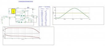
I came up with a 3 transistor class AA trans Conductance amplifier. It can generate odd harmonics of opposite phase 4.7% . Note on the harmonics table with respect to fundamental no 1. On scope you see instead of getting towards square wave , it tends towards triangular. Please comment critically as I didn't had time to see in all aspects.
Attachments
Hi,
Since we are at this topic, I would like to aks how do you simulate your distortion. I have tried with LTspice but the list of components available for transistors is very limited.
So I am looking for advice, how you guys do it?
Oon
Get a copy of Cordell-models.txt file for LTSpice. For ones not there, search DIYA. There is thread on models for obscure transistors. If still stuck, someone will usually help you find it.
- Home
- Amplifiers
- Solid State
- Suggestions for simple class AB with no global FB.