I have a stupid question. How do you import the models in? I notice that some manufacturers provide spice models but how do you add them into your model?
Oon
Oon
Member
Joined 2009
Paid Member
I haven’t put soldering iron to my attempt yet (TGM 11 amplifier) but if you are still looking for suggestions I started looking at a Class AB with no global feedback, no nested feedback, no feedback type error corrections or the like, just feedforward at the gain stage and some degenerative emitter followers. The building blocks have all been invented and proven by others.
https://www.diyaudio.com/forums/sol...inspired-steven-dunlap-krill.html#post5003698
https://www.diyaudio.com/forums/sol...inspired-steven-dunlap-krill.html#post5003698
Last edited:
I have a stupid question. How do you import the models in? I notice that some manufacturers provide spice models but how do you add them into your model?
Oon
Do a YouTube search - LTSpice makes videos showing you how to
do this step by step.
There is also an LTSpice thread where you can get help.
The main reason he needs no feedback loop , to have 0 damping factor . Your amp is low impedance. It must be tailored for 16 ohms with 500mv RMS (may be) for 10 watt output , and all this with 3 transistors if you please .I haven’t put soldering iron to my attempt yet (TGM 11 amplifier) but if you are still looking for suggestions I started looking at a Class AB with no global feedback, no nested feedback, no feedback type error corrections or the like, just feedforward at the gain stage and some degenerative emitter followers. The building blocks have all been invented and proven by others.
https://www.diyaudio.com/forums/sol...inspired-steven-dunlap-krill.html#post5003698
Just had a thought. What if I did the circuit as I described in my first post but used 3 diodes and at a resistor at the emitter to make it into an AB amplifier and use it in a bridge configuration ( 2amplifiers) with a bipolar cap in between, since it will be impossible to match the bias.Then build a simple one transistor phase splitter to create the out of phase signal. Do you think it would sound good?
Oon
Oon
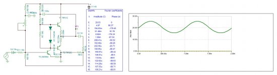
I simulated your circuit. The maximum output is 5V peak with 40v supply. 0.78w 4% Distortion.
I cannot make better than the class AA on post 19 . You don't like it?
I cannot make better than the class AA on post 19 . You don't like it?
Attachments
Last edited:
Hi,I simulated your circuit. The maximum output is 5V peak with 40v supply. 0.78w 4% Distortion.
I cannot make better than the class AA on post 19 . You don't like it?
On the contrary. I appreciate what you are doing. It is just that I cannot understand your circuit and how it works yet. So it becomes a big problem later when I try to optimise it or tune it. The problem with discrete circuits is you would need to understand how or else you will be in a really big mess when it is not working properly.
I think the simulation of the circuit i posted itself would yield very poor results. So it needs to be redesigned and optimised. I just copied from the internet to describe that kind of circuit. That design has insufficient bias. current from the driver. The moment the voltage start to swing too positive. The current through the resistor for driver becomes insufficient to drive the output transistor. The circuit will only work if the output transistor is replaced with a Darlington.
Incidentally what software are you using for your simulation?
Oon
Thanks I will check it out.Tina TI . Free from Texas Instrument. Simpler than LT but far more easier .
Oon
Happy with 1 to 2V rms. And it doesn't have to be 3 transistors. Can be more but not 20 + transistor...500mv sensitivity, is it your choice ? If not, would you coop with nowadays standard 2v RMS ?
I am actually looking a BTL. To get higher power, also BTL will result in some cancellation of distortion due to the symmetry.
Oon
Last edited:
Do happen I bought a box of it... yeah it is 16 ohms.Is your speaker 16ohms ?
Oon
In speakers the problem is voice coil resistance, which acts in series with the back emf generated by the coil, thereby, subtracting some of it for current to pass according to Ohm's Law. This leads to a current dependent voltage component that subtracts (phasor subtraction) from the real signal. If a speaker is properly designed, that should not affect sound reproduction quality.Mark Tillotson said:I think its more like high efficiency speakers have lower mechanical Q and can _tolerate_ a lack of electrical damping better than high-Q designs, but most normal speakers are designed assuming a stiff voltage source driving them. Nothing "dislikes" an accurate source signal!
This is why there is a vast choice of chip amplifiers. Feedback can be a nuisance, but if it is properly used, there should be no problems.Feedback is almost always a big advantage in an amp, and global feedback is often the most cost-effective topology as you benefit from more open-loop gain.
My experience is, when amplifiers used ony local feedback, the sound reproduction was not as good as it is today. This applies to transistor based amplifiers. I remember radio sets that used only local feedback, what I can say, they sounded poorly compared to what you get for the same price. I have in mind those radio audio amplifiers that used a transformer based push-pull output stage. They had a signal transformer used as a phase splitter and a push pull output stage.
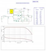
Here are 2v RMS sensitivity for 16 and 8 ohms.


Attachments
Last edited:
You want to understand the circuit before building it , you are right . But how are you ready for 20 transistor circuit when you cannot understand with 3.
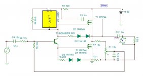
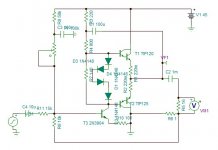
The circuit proposed in post #1 is essentially an input gain stage followed by a push-pull follower.
Output coupling is capacitive to allow for DC drift and single supply.
To have sufficiently low output impedance, the output devices need to be bipolar power transistors with little or no emitter degeneration.
Thermal run-away of the BJTs has to be taken care of in the biasing circuit (e.g. thermally coupled Vbe multiplier).
Since most power BJTs don't have hfe much higher than 100, Darlingtons or Sziklai's become unavoidable, practically.
Even then, the drivers need to have bias capable of > 20mA.
That in turn means that the gain stage should have a bias of ~5mA.
For 5~10W into 8R, you will need at least 24V for a single supply.
With 5mA bias, the collector (or drain) resistor should be ~2.4k.
For a gain of 10, the equivalent emitter (or source) resistance should be ~200R.
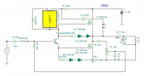
The attached spice file is nothing more than an illustration how it might be made to work.
But you will need to match hfe for Q2,Q4 & Q3,Q5.
And you need to have the right Idss for Q1 to get both the gain and the output DC where you want them to be.
So a bit fiddly, shall we say.
Q2~Q6 needs to be all thermally coupled, without saying.
And you will need to operate at rich Class A to get low distortion with no global feedback.
Cheers,
Patrick
.
Output coupling is capacitive to allow for DC drift and single supply.
To have sufficiently low output impedance, the output devices need to be bipolar power transistors with little or no emitter degeneration.
Thermal run-away of the BJTs has to be taken care of in the biasing circuit (e.g. thermally coupled Vbe multiplier).
Since most power BJTs don't have hfe much higher than 100, Darlingtons or Sziklai's become unavoidable, practically.
Even then, the drivers need to have bias capable of > 20mA.
That in turn means that the gain stage should have a bias of ~5mA.
For 5~10W into 8R, you will need at least 24V for a single supply.
With 5mA bias, the collector (or drain) resistor should be ~2.4k.
For a gain of 10, the equivalent emitter (or source) resistance should be ~200R.
The attached spice file is nothing more than an illustration how it might be made to work.
But you will need to match hfe for Q2,Q4 & Q3,Q5.
And you need to have the right Idss for Q1 to get both the gain and the output DC where you want them to be.
So a bit fiddly, shall we say.
Q2~Q6 needs to be all thermally coupled, without saying.
And you will need to operate at rich Class A to get low distortion with no global feedback.
Cheers,
Patrick
.
Attachments
- Home
- Amplifiers
- Solid State
- Suggestions for simple class AB with no global FB.