One would think if TI was responsible enough and acknowledge the issues, they would screen the parts so the customers would not have to be burden with the cost of screening themselves, shame on TI.
I searched TI's web site regarding this issue, there are two threads both are locked,
[Resolved] LME49720: popcorn noise - Audio forum - Audio - TI E2E support forums
LME49720: Pop-cone noise - Audio forum - Audio - TI E2E support forums
I take it as they know it is a problem and chose to do nothing about it or there answer is thatthe customer is responsible to test/grade and they will offer replacements as their solution.
Does it really matter? I hear so badly between 0 and 20 hertz.
This effect also occurs with poor grounding (ground loops / no star grounding).
Last edited:
In the new version I have now also included a box for the DUT gain. But I'm not sure what kind of influence a DUT gain has on the THD measurement. Maybe someone can give me a hint if my implementation / assumption is correct.
Attachments
Last edited:
Does it really matter? I hear so badly between 0 and 20 hertz.
True popcorn noise is statistically unpredictable and the pops can be significant sudden jumps in level and have spectral content across the entire audio range. Some of the plots here look more like GR noise which is distinctly different and more like an increase of low frequency noise which would not always be obviously audible.
hmmm arent we talking about what the referene level is -- the fundemental?
FS would refer to the input... or zero level. If fund is 1v then that is the FS ref to. dBr is OK also.
Carrier doesnt work for me unless I am talking about modulated signals.
-RM
Phase noise is measured in dBc. No modulation, just the noise and how it relates to the oscillator peak level.
//
But, the pop corn noise may be significant in the case of the oscillator and it's measurement. The AGC may reacts to the "pop corn" and the result is the output gain fluctuations, but the measured spectrum has a "tail" mainly at low frequency region, which randomly dances up and down.Does it really matter? I hear so badly between 0 and 20 hertz.
This effect also occurs with poor grounding (ground loops / no star grounding).
I know the dancing hum. I should switch to OPA1656...But, the pop corn noise may be significant in the case of the oscillator and it's measurement. The AGC may reacts to the "pop corn" and the result is the output gain fluctuations, but the measured spectrum has a "tail" mainly at low frequency region, which randomly dances up and down.
All the parts work in one system. When we change ones, then needs to correct others. As example, when we lower the resistors in the linear inverter, then needs to lower also the AGC FET transistor minimum resistance, but it works near the limit.Well, mai you also consider to lower the LDO resistors to 1K ohms direction? The values should be large enough so noTHD is product to drive the R/C filter.
Also both parts of the filter uses none equal R/C values.. Why?
Hp
The oscillator consists from two inverters. Each of them has gain -1. Needs to use different RC values (1:2) for to get that gain from the filter inverter. This is classical schematic.
This design has been optimized for the best performance/cost ratio. You may get a little better performance, but lose a lot more money.
part of the problem for me is that the LM4562 is one of the last high quality pdip8 parts available. I use things like it for lower offset in replacement situations, allowing for elimination of capacitors in some situations. Adapters are fine for onesy twosy, but I sometimes replace dozens, not exactly time or money efficient.
Cheers
Alan
Cheers
Alan
Maybe use pcb-only adapter withhout pins, just pads cut in half, should be fine for 2-layer boards with metallization. (pcb edge pads)
Might be even more efficient than dip package (no need to flip the board to solder). Extra "nice to have" - use thin (0.6mm) pcb for adapters, could be easily cut and doesn't add much lead inductance. You can make 1000s of these just for $10 or less))
Might be even more efficient than dip package (no need to flip the board to solder). Extra "nice to have" - use thin (0.6mm) pcb for adapters, could be easily cut and doesn't add much lead inductance. You can make 1000s of these just for $10 or less))
Fully agree. If you have a toolbox, use the best tool for the job at hand. Tools have no intrinsic value, the value is in the way they help you get the job done 😎
Jan
My point exactly.
Cheers,
In the new version I have now also included a box for the DUT gain. But I'm not sure what kind of influence a DUT gain has on the THD measurement. Maybe someone can give me a hint if my implementation / assumption is correct.
I don't think it has an impact on the measurement. That is clearly defined: you measure the level of the harmonics in the signal with respect to the level of the fundamental. That definition doesn't change with DUT gain.
Jan
I'm not very clear. What happens if the DUT has a -6dB attenuation at the input? The harmonics are then smaller and a better value is determined. What happens if the attenuation happens at the DUT output? The harmonics would then be smaller and the measured value better than the reality. Would not the DUT always have to be unity gain?I don't think it has an impact on the measurement. That is clearly defined: you measure the level of the harmonics in the signal with respect to the level of the fundamental. That definition doesn't change with DUT gain.
Jan
If the harmonics dB values are calculated against the fundamental (as 0dB), then IMO the actual level of the fundamental does not matter. That is what REW lists in the distortions table, IMO.
I'm not very clear. What happens if the DUT has a -6dB attenuation at the input? The harmonics are then smaller and a better value is determined.
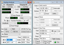
This is the exact reason why you MUST have a reference. If your software measures dBV it assumes that the fundamental is at 1V. If the fundamental is not at 1V, you must somehow tell the measurement software what it is. dB is not some absolute value, it is a ratio, a 'A/B' value where one is the fundamental and the other the harmonic. You always need TWO values to make a dB measurement meaningful.
One way to tell the measurement software what the fundamental is in the AP software is to select the Y-axis in dBr and set the fundamental value in a box called 'dBr'. See attachment, top right to select the scale, bottom left to set the actual reference.
I don't know how your software does it, but in your gadget you must accommodate it.
Once you get your head around that dB is just a ratio, you can juggle it any way you want.
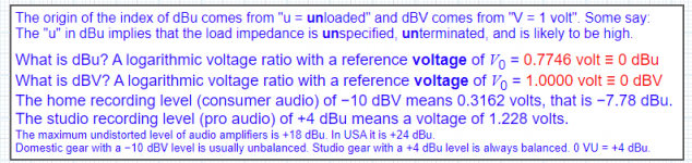
You can use dBm, which is dB referred to a voltage that puts 1mW in 600 ohms, not used a lot anymore but not better or worse than any other dB 'type'. I won't go into dBc anymore as some here seem allergic to it, but it is just another way to refer to the fundamental level.
And don't get me started on dBu ...
Jan
Attachments
Last edited:
Hi Jan,You can use dBm, which is dB referred to a voltage that puts 1mW in 600 ohms
Throwing these terms around loosely can be misleading.
As I am sure you know, maybe others do not, in the RF world 0dBm is 1mW into 50 ohms.
I guess the idea is if you are going to use a reference, then explicitly state what it is, so there is no confusion.
Other than that everything is relative.
Rick
Last edited:
If the harmonics dB values are calculated against the fundamental (as 0dB), then IMO the actual level of the fundamental does not matter. That is what REW lists in the distortions table, IMO.
Correct, but note that the level of the fundamental is still needed for the calculation of how much the harmonic is below it. But yes, if the software can measure the fundamental and declare that to be '0dB' then you don't have to enter it, and harmonic distortion can be reported in dB without suffix, or in dBc, distortion with respect to the fundamental level. 😎.
Jan
Hi Jan,
Throwing these terms around loosely can be misleading.
As I am sure you know, maybe others do not, in the RF world 0dBm is 1mW into 50 ohms
Rick
Yes, that is the difference between RF and audio. Since we will generally talk about audio here, I used the audio-related definition.
dBm - Wikipedia
But the point I was trying to make is that dB value are only meaningful if you have a reference, and the x in dBx can be used to indicate the reference.
Can I go play now? 😎
Jan
But yes, if the software can measure the fundamental and declare that to be '0dB' then you don't have to enter it, and harmonic distortion can be reported in dB without suffix, or in dBc, distortion with respect to the fundamental level. 😎.
Jan
Sure, that is what REW does:
https://www.diyaudio.com/forums/att...ensation-measurement-setup-splt-vd-256fft-png - the harmonics plotted the chart are dBFS, while the harmonics listed in the table are plain dB - against the fundamental (0dB). It makes sense because the harmonics are located automatically for the detected fundamental.
Of course if a notch filter is involved, the whole situation changes...
- Home
- Design & Build
- Equipment & Tools
- Low-distortion Audio-range Oscillator