First off my skills.
I can solder, measure voltages using a meter. I have recapped a Pioneer SX-1050. Troubleshooting skills in non existent. I just replaced parts based on the schematics and or instructions from forums.
I read a lot of good reviews on the performance of the Glass ware 12ac Aikido pre. I am a just a bit concerned about the documentation/schematics that is included in the kit. I have heard that there are several errors on the documentation.
Does anyone know if the documents / schematics / manual has been updated ?
Don't listen to gossip. "I have heard" without sources or other documentation is gossip.
I have good experience of their kits, go for it !
I have good experience of their kits, go for it !
Their kits are very high quality. Study the schematic and parts before starting.
You can post any questions here before assembly.
You can post any questions here before assembly.
I built one of these. The only error in the documentation was that it suddenly cut off near the end. The parts are all neatly labeled as is the circuit board, so no problems putting everything together.
I've built a couple Aikido's. I'm pretty sold on them. First I built a 12au7 version, then a 12ax7 version. The one I'm using now uses 6sn7 octals. I'm perfectly happy with the latest one. I've used and built other preamps, but the Aikido is by far my favorite.
Have fun with your build!
Have fun with your build!
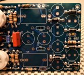
I have assembled my unit, this is the 6dj8 Version which requires the 12v ac transformer
target is 80V for B+ and 25.v for heater voltage
These are my measurements
Without Tubes
Voltage across C2 B+ 104v
Voltage across C10 heater 26.6v
With Tubes
Voltage across C2 B+ 93.8
Voltage across C10 heater 19.6
target is 80V for B+ and 25.v for heater voltage
These are my measurements
Without Tubes
Voltage across C2 B+ 104v
Voltage across C10 heater 26.6v
With Tubes
Voltage across C2 B+ 93.8
Voltage across C10 heater 19.6
Last edited:
In the spirit of DIYaudio … could you include a schematic, so that C₂ and C₁₀ actually can be visualized?
B+ of 104 volts unloaded, and 94 volts loaded does not sound out-of-spec. If there is a resistive hum-filter in the power supply, a –10 V drop is fairly usual. Can't say much about your C₁₀ measurements without a schematic diagram. Capturing with your smart phone would be good enough!
Just saying,
GoatGuy ✓
Input voltage is 12.8v
Measured the voltages again without changing anything. I noticed R15 (47ohms) was getting really hot that I could not touch it and it started to smell 🙁
I replaced R15 with the physically larger 20 ohm resistor and it gets hot after 30 seconds or so. Without the tubes, R15 does not get hot as much
Voltages after I replaced R15, Tubes installed
Voltage across C2 B+ 94
Voltage across C10 heater 23.4
Voltage across R15 10.8v
Without the tubes, measurements below
Voltage across C2 B+ 103.6v
Voltage across C10 heater 26.8v
Voltage across R15 7.2v
Do you mean a 2 amp fuse?
Steve
Yes, 2 amps
I initially did my testing/measurements without the fuse.
I mean 2 amp fuse...
EDIT: I inserted a 2 amp resistor on the secondary and it blows
It's possible to blow a 2 amp fuse in the secondary. Fuse the primary side of the power trans with about a 1/2 amp slow blow fuse.
Your voltage readings with the 20 ohm resistor are about correct. Yes this resistor will get warm. You will need a 5 watt resistor here. I used two 51 ohm, 3 watt res in parallel here, equivalent to 25.5 ohm. 6 watt res. Theses still get warm. So if you want it to run cool a 10 watt res ( or 2 5 watt in parallel) might be the best for R15.
See these articles for assembly and test:
Battle of the Cheap Line Stages – Part 1 | Wall of Sound | Audio and Music Reviews
Battle of the Cheap Line Stages – Part 3 | Wall of Sound | Audio and Music Reviews
Battle of the Cheap Line Stages, Part 4 | Wall of Sound | Audio and Music Reviews
Steve
Thanks !!!
This is the resistor that came with the kit, wattage was not stated in the plastic bag that came with it
r15 resistor - Imgs.info
This is the resistor that came with the kit, wattage was not stated in the plastic bag that came with it
r15 resistor - Imgs.info
If you spin vinyl and are feeling brave the Broskie Tetra phono pre is a good project.
Fist of five parts detailed here:
DIY All-Tube Phono Preamp Project: It’s on! | Wall of Sound | Audio and Music Reviews
Steve
Fist of five parts detailed here:
DIY All-Tube Phono Preamp Project: It’s on! | Wall of Sound | Audio and Music Reviews
Steve
Tried vinyl a few years ago and found out that I could not live without the skip button 🙂
If you spin vinyl and are feeling brave the Broskie Tetra phono pre is a good project.
Fist of five parts detailed here:
DIY All-Tube Phono Preamp Project: It’s on! | Wall of Sound | Audio and Music Reviews
Steve
Might be a five watt resistor, might only be a three. It will get warm. The ones I used were wirewound so they are "meant" to get hot. If the one with the kit burns up you'll know you need something with a higher wattage rating. As a tip for next time keep this resistor up off of the board about an inch to aid it heat dissipation.
Also, it's a good idea to solder the component leads on both sides of the board whenever possible. I like to keep the large diodes above the board a bit too as they can get a bit warm.
S.
Also, it's a good idea to solder the component leads on both sides of the board whenever possible. I like to keep the large diodes above the board a bit too as they can get a bit warm.
S.
Attachments
- Home
- Amplifiers
- Tubes / Valves
- Glass-ware Aikido 12vac build