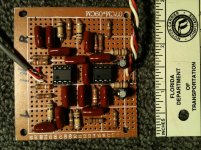
Speaking about Phono Preamps...... and Veroboard... I just finished making the Project 99 - Sallen-Key Subsonic Filter by Rob Elliot to add onto a Harman Kardon 330A receiver. I wanted it to be as compact as possible, to mount on the reverse side of the phono preamp mounting panel.
I've made and installed these filters on several things so far with excellent results. It effectively removes any audio below 20 Hertz, which is unneeded anyway - turntable rumble, record warp issues, and bass speaker feedback issues. You can't even notice any audible difference in the audio, and it helps eliminate that power-robbing subsonics in the amplifier.
I've made and installed these filters on several things so far with excellent results. It effectively removes any audio below 20 Hertz, which is unneeded anyway - turntable rumble, record warp issues, and bass speaker feedback issues. You can't even notice any audible difference in the audio, and it helps eliminate that power-robbing subsonics in the amplifier.
Attachments
Hey guys,
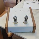
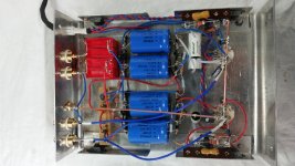
So I finally finished building this phono preamp.
It sounds great.
I'm using a switching power source as a temp power supply. I mentioned it earlier. I'm getting a buzz that sounds like a bee. I believe it's coming from the power supply, so this power supply will only be temporary.
I will build the one recommended on this thread for this phono stage.
This is my first build from scratch, and I'm very happy with the results.
Attachments
IIRC, fellow Torontoian kodabmx is experienced with SMPS powered tube circuitry. Perhaps he can help you get rid of that buzz.
Thank you, I'll see if he has some advice for my situation.
For now I'm just enjoying the phono stage as is.
For now I'm just enjoying the phono stage as is.
So I've met up with Greg now. His 12V supply was too small and wouldn't start. I had a 6A version which started into the load. There was still motorboating. I added a 2k/100uF RC filter to the supply which solved the issue when using both SMPS, one for heaters, and the other for B+. When he got it all home and tried just the single supply, it was motorboating again.
The circuit is drawing 30mA @ 250V. This seems high to me (my 8 tube phono only needs 50mA). Maybe Eli can comment? I've never built a hybrid. It would also motorboat without the tubes, just the MOSFETs, before I added the RC filter.
The circuit is drawing 30mA @ 250V. This seems high to me (my 8 tube phono only needs 50mA). Maybe Eli can comment? I've never built a hybrid. It would also motorboat without the tubes, just the MOSFETs, before I added the RC filter.
Last edited:
30 mA. seems large. The 12AX7 sections should draw between 900 μA. and 1 mA. each. The buffering FETs draw approx. 2 mA. each. So, 30 mA. is easily 3X what should be measured. There's a "leak" to be tracked down.
Hopefully Greg and I can meet again soon. I didn't even open the phono amp. I modified the external power supply. But a 2k resistor that I added is dropping ~60V. Thanks for the info, Eli. I guess we'll have to open it up and do some useful measurements... Any reason you didn't design this using a depletion MOSFET like DN2540?
> a 2k resistor that I added is dropping ~60V
That's absurd and obscene.
It smells like a 10K resistor slipped in where should be a 100k.
Since even a shorted-load 12AX7 can't pull many mA, it also suggests the wrong value may be on a MOSFET?
The other possibility is a reversed mis-rated, or bad filter cap. However 7 Watts in a small can should "expose itself" (and its guts) in a few minutes (if the power supply holds it up long enough to burst).
Any reason you didn't design this using a depletion MOSFET like DN2540?
DC coupling an enhancement MOSFET to a tube's plate is a total "no brainer". You know the voltage on that plate and, therefore, the voltage on the gate. You know the B+ rail voltage and, therefore, the voltage on the drain. The source sets up a little below the gate, in order for the necessary forward biasing to be present. The difference between gate and source can be ignored. Pick a safe drain current and use Ohm's Law to calculate the load resistor's value.
The capacitances of the ZVN0545A are tiny. Even a wimp, like the 'X7 triode, has no problem driving them.
The "gotcha" in this topology is the fact that FETs are instant on and tubes need time to start conducting. A Zener diode clamp between gate and source keeps the FET safe, until tube conduction starts.
But this particular application doesn't appear to need the gate-source protection.The "gotcha" in this topology is the fact that FETs are instant on and tubes need time to start conducting. A Zener diode clamp between gate and source keeps the FET safe, until tube conduction starts.
The N-channel part can stay at B+ all day(like it would with a cold or missing tube) and it won't care because the load is under it and resistance is huge compared to the internal resistance of the FET. Swap the FET with R5 and use it how n-channel parts are normally used(source tied to ground) you'd kill it every time you tried to fire it up without protection.
Now, a quick solid state supply and a short on the output might kill it on startup like it is but otherwise this design is safe.
Do you have a schematic with it added? The one I've seen going around doesn't have that part included.
Good news. After looking at the RC filter it turns out it's a 10k resistor not 2K. so that brings the draw to 5.6mA. not 30. much more acceptable.
Still need to sort out the motor boating though.
Still need to sort out the motor boating though.
Ya I don't know how I missed that other than the 10k resistors are in the drawer under the 2k...
So what are the voltages before and after the 10k resistor, Greg?
So what are the voltages before and after the 10k resistor, Greg?
You have external smps power supplies right? Did you put a local B+ supply capacitor in the chassis where the FET is connected?
Koda,
I get 300v before the 10k resistor and 250 after.
kylej1050
the smps power supplies are external. Just mounted on some wood for now. I followed the schematic that was posted earlier on this thread. I used 30uf decoupling caps in the unit.
I get 300v before the 10k resistor and 250 after.
kylej1050
the smps power supplies are external. Just mounted on some wood for now. I followed the schematic that was posted earlier on this thread. I used 30uf decoupling caps in the unit.
The added RC filter is external to the amp, the amp has whatever it was designed with inside it though.
Now that we know the circuit is running property current wise, we can ad a zener string to regulate to 250V instead of relying on the adjustable SMPS. I highly doubt it would motorboat with the type I showed you that is fixed but adjusted with a jumper, either. Especially that you got the +- supply rather than the + only, and you aren't loading the - side.
Now that we know the circuit is running property current wise, we can ad a zener string to regulate to 250V instead of relying on the adjustable SMPS. I highly doubt it would motorboat with the type I showed you that is fixed but adjusted with a jumper, either. Especially that you got the +- supply rather than the + only, and you aren't loading the - side.
Great. Glad there's a solution, the motorboating got louder to a point where i can not enjoy the music.
Hey Guys,Each channel has its own set of decoupling parts. A single power trafo, rectifier, and filter is fine. Use individual LR8 regulators in each channel.
A schematic for a modest cost/high performance PSU is provided.
I'm looking at building this power supply. I'm starting to look at the Mouser website to order parts. In the Schematic There's a 7812 regulator that needs a heat sink. This is in the 12v section. The notes at the bottom right say to use a MEDIUM sized heat sink on LM7812
Does this regulator look ok? LM7812CT/NOPB Texas Instruments | Mouser Canada
How about these heat sinks, would any of these be OK? I'm not sure what constitutes a med sized heat sink. EX Series Stand Up Heatsinks - Ohmite | Mouser Canada
Do the LR8N3 regulators also need a heat sink? It lists a T0-92 on the schematic. I can't find anything under that number.
- Home
- Amplifiers
- Tubes / Valves
- Eli Duttmann's phono preamp voltages