IIRC KSTR's amp was for a nearfield monitor. I don't think he said much about specs, but I think you do lose some benefits of current drive in the transition band. It's difficult to make the transition steep enough to get significant impedance in the area above Fs.
Oh. OK. Dont forget the driver though. Simple amp mods we know about, already.If simple amp mods can tame existing speaker design issues, why not? You keep asking how to make the perfect driver..working on both is viable.
Jn
RNM
Last edited:
Go ahead, but remember that this struggle caused by the >1W signal THAT is demonstrated percentually covers most of the playback time is just an academical job, also the modern speakers are perceptually better at doing it, to support the peaks. Aren't them ?
( Oh ! THAT causes the research 🙄 sorry )
Most of the non-linear variations are caused by the air load on the back, go figure...
🙄😕
Most of the speakers are used in BR boxes which makes the driver resonate, isn't it ? The chaotic motion of particles inside the box should not have anything to do with the ordinate emission of the front/forward side
You are only stirring a pot - with elementaries. The methods linked are to measure frequency response, not distortion. Learn before you say "do it right".<snip>
An so-called anechoic chamber attenuates (above a low frequency limit given by the chamber dimensions) all reflections strongly, so any other measurement method that attenuates reflections strongly or avoids them (or let them appear only after a very prolonged time span) will lead to the same advantage.
Leaving resonant devices aside, a room does not create distortions itself, it makes measurements more difficult when modes impact the reference level (from which the distortion number is derived) or destructive/constructive interference with reflected waves does the same. Most of these effects can be sorted out but it is quite tedious, so using of any other measurement methods avoiding these effects does help.
You cannot use impulse response windowing if you still want to see distortion components properly. The time window would be too long an would eliminate windowing smoothing effect. Windowing can be used only to smooth FR. Yes room issue are the reflections and modes that destroy precision of LF distortion measurement and so it is made in near field if in the room. Plenty of literature on this.
yes works fine EXCEPT the power level to reach 80-90db spl is too low when measurment mic is close to driver.You cannot use impulse response windowing if you still want to see distortion components properly. The time window would be too long an would eliminate windowing smoothing effect. Windowing can be used only to smooth FR. Yes room issue are the reflections and modes that destroy precision of LF distortion measurement and so it is made in near field if in the room. Plenty of literature on this.
If you put 10W or more with mic up close, the mic could overload/distortion is high. Only with expensive specialised mic can handle those spl at low distortion.
Better to use 10W or more testing with mic much further away and still at 80-90db spl. To measure at more realistic power levels into driver, it is more practical to be out doors at further distance.
Thx-RNMarsh
Last edited:
For all who are interested, Microcap is now free.
Spectrum Software - Micro-Cap 12. Analog simulation, mixed mode simulation, and digital simulation software. SPICE and PSpice(R) compatible circuit simulator.
Micro-Cap User Downloads
Spectrum Software - Micro-Cap 12. Analog simulation, mixed mode simulation, and digital simulation software. SPICE and PSpice(R) compatible circuit simulator.
Micro-Cap User Downloads
Last edited:
Keele on LF nearfield measurement:
https://www.pearl-hifi.com/06_Lit_A...apers/Keele_D_B/LF_Near-field_Measurement.pdf
https://www.pearl-hifi.com/06_Lit_A...apers/Keele_D_B/LF_Near-field_Measurement.pdf
Distortion Because of relation (5), completely valid measurements of low-frequency harmonic distortion can be made in the nearfield and these should correlate well with an identical set of measurements in the farfield if all distortion components are within the specified frequency limit. Somewhat lower nearfield distortion values are to be expected where distortion harmonics exceed this limit. The relatively high SPL found in the nearfield of a piston can actually aid distortion measurements because the acoustic signal-to-noise ratio is much improved. In most cases, meaningful distortion tests can be made even in a noisy laboratory environment.
Yep, while it seems possible to implement very high rates of change by using, say, a notch filter at resonance on the current signal and a corresponding peak filter on the voltage before summing them (maintaining linear phase of the total, of course) I haven't tried that yet and restricted myself to 1st order slopes, that is, the output impedance becomes inductive above resonance until it settles at a "large enough" resistive value (some ten's of ohms). I have a gut feeling that "over-inductive" slopes might result in some unexpected side effects and (dynamic) instabilities and even without these, the actual improvement, if any, might be small, but as I said, I haven't tried this... on the to-do list though...IIRC KSTR's amp was for a nearfield monitor. I don't think he said much about specs, but I think you do lose some benefits of current drive in the transition band. It's difficult to make the transition steep enough to get significant impedance in the area above Fs.
Keele on LF nearfield measurement:
https://www.pearl-hifi.com/06_Lit_A...apers/Keele_D_B/LF_Near-field_Measurement.pdf
Nope. Power level too low. Accurate for those conditions. But we need more realistic conditions.
'Some what' is an understatement for many speakers --> Somewhat lower nearfield distortion values are to be expected where distortion harmonics exceed this limit.
The crux of the problem.... and now 2.8v/8 (1W) is a norm for this type of testing.
If you are happy with (IMO unrealistic) small signal distortion levels, so be it.
I am not.
I have made my point.
THx-RNMarsh
For all who are interested, Microcap is now free.
Spectrum Software - Micro-Cap 12. Analog simulation, mixed mode simulation, and digital simulation software. SPICE and PSpice(R) compatible circuit simulator.
Micro-Cap User Downloads
Holy Cow! One of the very best. I have used it and updated it for years ($$$). Lot of designers use it -- Doug Self etal.
I am going to down load ver 12 asap before the site goes away.
Thank you for this timely info. WOW 39 years! Time to retire, I'm sure.
-Richard
🙂
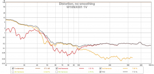
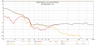
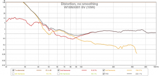
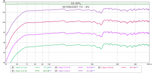
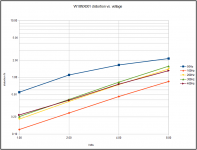
A set of nearfield distortion measurements of Seas W18NX001 in a vented box, from 1Vrms to 8Vrms. Driver impedance is 6ohm approx., so it is up to 10W el. We can see that though distortion under resonance is terrible, the driver behaves nicely above 50Hz with distortion not exceeding 2% at 10W from 50Hz upwards. This is a good result and such a small driver will not be asked to play 20Hz in a reasonably designed box. FR added, port not measured. SPL not calibrated.
Attachments

Last edited:
Very nice, PMA. 8v is about 8 times higher distortion compared to 1v.
Under 2% is a very good driver performance for a 7 inch ...... $206 USD.
SEAS Excel W18NX-001 (E0042) Nextel Cone 7" Woofer
How do we get the distortion lower? If this was an amplifier, we would not buy it.
Got IM, also?
THx-RNMarsh
Under 2% is a very good driver performance for a 7 inch ...... $206 USD.
SEAS Excel W18NX-001 (E0042) Nextel Cone 7" Woofer
How do we get the distortion lower? If this was an amplifier, we would not buy it.
Got IM, also?
THx-RNMarsh
Last edited:
Now, a point to ponder...
Can an amplifier be reliably designed such that below say 1 to 2Khz it operates using voltage feedback, and above it gradually switch to current feedback?
That would remove the hf dissipative losses from the transfer function, but still provide voltage control through resonance and no issues with thermal runaway.
jn
Yes, did it with LM3886 according to this setup. Remember the schematic I showed a while back for an amp with adjustable Zout? In each leg of the voltage divider, one can include a low and high pass side. This one has current drive below 3 kHz and voltage drive above. Ratio between R's in voltage and current leg should be equal, so not a 1 amp for all drivers solution.

Any full range music system ought to play 40Hz cleanly (pref to 30Hz) 10% distortion at 40Hz is nothing to get excited about in a bass driver. How do we lower the LF distortion? JN?Very nice, PMA. 8v is about 8 times higher distortion compared to 1v.
Under 2% is a very good driver performance for a 7 inch ...... $206 USD.
SEAS Excel W18NX-001 (E0042) Nextel Cone 7" Woofer
How do we get the distortion lower? If this was an amplifier, we would not buy it.
Got IM, also?
THx-RNMarsh
THx-RNMarsh
jneutron, is this the eddy current variable damping you were talking about?
Yellow trace is the voicecoil current.
Red trace is voicecoil motion.
Orange trace is the magnetic force opposing the motion of the coil.
Took me a while to figure out what you were doing. I think I understand. You are showing the magnetic braking of the 1kHz mechanical movement on a quasi DC driven coil. It looks very good.
My initial thinking was along the lines of both signals on the coil, huge LF motion, and times when the velocity caused by both cancel. So depending on which way the LF excursion is going, opposite polarities of the hf motion would have higher drag.
Nice.
Jn
Last edited:
A set of nearfield distortion measurements of Seas W18NX001 in a vented box, from 1Vrms to 8Vrms. Driver impedance is 6ohm approx., so it is up to 10W el.
We can also see that, above resonance, distortion rises almost linearly with voltage, up to measured 8V / 10W. At resonance and below, cone excursion is so big that the speaker coil travels out of the linear zone.
Attachments
Keele on LF nearfield measurement:
https://www.pearl-hifi.com/06_Lit_A...apers/Keele_D_B/LF_Near-field_Measurement.pdf
Which illustrates why I was wondering about your response to RNMarsh's links; I remember when reading Keele's article for the first time (around 1984/5 IIRC), it was a nice revelation/solution for the low frequency measurement problem.
It follows the same route (different receipt though), every method that blends out (attenuates strongly) the impact of modes and reflections will be beneficial for distortions measurements.
Yes but RNM takes strong exceptions to near field measurements, that's why I linked the Keele JAES paper.
Most of the non-linear variations are caused by the air load on the back, go figure...
🙄😕
Both the driver and the air in the box resonate. The air in the box resonates as a Helmholtz resonator at a lower frequency than the driver's resonance, with the purpose of extending the low frequency response.Most of the speakers are used in BR boxes which makes the driver resonate, isn't it ?
I don't see where particle motion in the box is chaotic, but ...The chaotic motion of particles inside the box should not have anything to do with the ordinate emission of the front/forward side
Would a driver in a box containing a vacuum perform better (other than the detail of atmospheric pressure pressing at up to 14PSI on the front)?
Doing this, since the volume of vacuum behind the driver has no effect, the box could be small, just large enough to hold the driver.
Counteracting atmospheric pressure is, of course, left as an exercise for the reader.
Last edited:
Immerse the entire speaker in vacuum.Counteracting atmospheric pressure is, of course, left as an exercise for the reader.
😀
Last edited:
- Status
- Not open for further replies.
- Home
- Member Areas
- The Lounge
- John Curl's Blowtorch preamplifier part III