yes. it is sound that is reflection free, thats all.What's the sound in an anechoic chamber? Is it sound!?
----------------------------------------------------------------------------------------------
Most are using something like MLS and windowing and a lot of processing. I bought the very first MLS product by DRA Labs and used it extensively.... back in the day.
Just get the drive level up to the speaker well above 1W and have a very low distortion microphone system. But the ground plan method anyone can do easily also.
THx-RNMarsh
Last edited:
You are only stirring a pot - with elementaries. The methods linked are to measure frequency response, not distortion. Learn before you say "do it right".An overview on correct measurements proceedures without an anechoic chamber..... some more on out side loudspeaker testing:
Ground Plane Measurements for optimiziing an loudspeaker
Subwoofer Measurement Tactics: A Brief, Topical Overview & Method Comparison | Audioholics
ETC
THx-RNMarsh
You need to find a way to get it done.
You need to find the way, not me. It is YOU who is requesting, so do the job. You are a renowned audio designer.
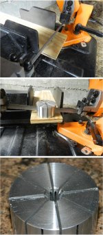
Here are pics of the setup.How did you get the super thin metal on the sides? Bandsaw? Slitting saw? Sheet metal and glue?
The pin on plywood, how the saw cuts, and a detailed look at the end showing how much aluminum is left at the center.
jn
Attachments
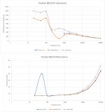
Here is the first pass measurements of the visaton BG20-8.
Inductance full scan:
On the first, the free air numbers go bonkers below 1K, wildly swinging from -77 mH to +10 mH.. so I didn't put them in to preserve scaling.
Note the facedown (orange) is reasonably behaved. To lock the cone (grey), I placed the woofer face down on a plastic electrical tape container. I think it was touching the cone, but it may have been touching the whizzer. So it's not very well locked, but it's all I had at the location to use.
The higher inductances "locked" are probably due to the fact that I had the cone pushed into the gap a bit, so this should be the expected Le(x) rise with position.
I will still go better on the locking before I disassemble the speaker. I suspect it will go monotonic slope when I hold it very tightly.
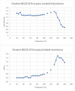
Resistance:
Free air resonance is very clear, but I did not do a tighter zoom there, so 50Hz is not the resonance, just the closest to it. Note also that the "locked" resistance from 2Khz up is leaving the free and facedown numbers. Something is causing extra hf dissipation as the voice coil moves into the magnet structure.
The second is a zoom in on the 20 to 160 Hz "locked" readings. I suspect there are cone vibes involved messing the readings.. But you had asked, so I gave it a shot.
I will be making the proper fixture for locking the cone and positioning it to various locations.
When I look at the typical speaker curves showing impedance and phase, I never get a sense of what is really happening energy wise. Clearly for this speaker, the increase in resistance from 5Khz up looks to be a function of dissipation external to the voice coil. I expect to eliminate that with a tap coil using jn drive, and it should also be countered by current drive.
jn
Inductance full scan:
On the first, the free air numbers go bonkers below 1K, wildly swinging from -77 mH to +10 mH.. so I didn't put them in to preserve scaling.
Note the facedown (orange) is reasonably behaved. To lock the cone (grey), I placed the woofer face down on a plastic electrical tape container. I think it was touching the cone, but it may have been touching the whizzer. So it's not very well locked, but it's all I had at the location to use.
The higher inductances "locked" are probably due to the fact that I had the cone pushed into the gap a bit, so this should be the expected Le(x) rise with position.
I will still go better on the locking before I disassemble the speaker. I suspect it will go monotonic slope when I hold it very tightly.
Resistance:
Free air resonance is very clear, but I did not do a tighter zoom there, so 50Hz is not the resonance, just the closest to it. Note also that the "locked" resistance from 2Khz up is leaving the free and facedown numbers. Something is causing extra hf dissipation as the voice coil moves into the magnet structure.
The second is a zoom in on the 20 to 160 Hz "locked" readings. I suspect there are cone vibes involved messing the readings.. But you had asked, so I gave it a shot.
I will be making the proper fixture for locking the cone and positioning it to various locations.
When I look at the typical speaker curves showing impedance and phase, I never get a sense of what is really happening energy wise. Clearly for this speaker, the increase in resistance from 5Khz up looks to be a function of dissipation external to the voice coil. I expect to eliminate that with a tap coil using jn drive, and it should also be countered by current drive.
jn
Attachments
Last edited:
You will understand the connection if you think a little longer about it.You are only stirring a pot - with elementaries. The methods linked are to measure frequency response, not distortion. Learn before you say "do it right".
-RNM
I have already done it. See #28704 aboveYou need to find the way, not me. It is YOU who is requesting, so do the job. You are a renowned audio designer.
Your turn
-RNM
Is there any back emf occuring near resonance? What is source Z to the driver?Here is the first pass measurements of the visaton BG20-8.
Inductance full scan:
On the first, the free air numbers go bonkers below 1K, wildly swinging from -77 mH to +10 mH.. so I didn't put them in to preserve scaling.
jn
If you have anything other than near zero Z driving the speaker, from test gear and/or cables to dut etc, you'll get that effect as you will also trying to do THD. I recently mentioned this and you asked if it was real.... It only does that when near or approaching resonance. Maybe we will get an explanation from your work.
But it seems certain test gear which has phase sensitive circuitry is fooled by the back emf signal and doesnt know which to lock on to.
-RNM
I already explained it a while back. The phase crosses through zero but the meter is designed to report exactly what it sees and does not take the absolute value. It does not understand that this is a mechanical energy storage/return. Some meters will do the absolute thing.
As to source Z, who knows. It's an HP 4284A.
For these scans, the really important stuff is the dissipative hf loss as shown by increasing resistance, and the change in hf dissipative loss when the voice coil is moved in the gap.
jn
As to source Z, who knows. It's an HP 4284A.
For these scans, the really important stuff is the dissipative hf loss as shown by increasing resistance, and the change in hf dissipative loss when the voice coil is moved in the gap.
jn
Last edited:
You are only stirring a pot - with elementaries.
I'm enjoying the popcorn on this one.
I already explained it a while back. The phase crosses through zero but the meter is designed to report exactly what it sees and does not take the absolute value. It does not understand that this is a mechanical energy storage/return. Some meters will do the absolute thing.
As to source Z, who knows. It's an HP 4284A.
jn
I have same HP but one model earlier and Stanford Research as well. Your source Z is 100 Ohms. It is highly sensitive to back emf from dut..
Thx,
RNM
The manual is in my other office, I will look through it. I believe their test methodology is impervious to back emf. It is not trying to control the dut, it is just driving it and comparing the voltage to current. HP would never assume a voltage, they measure everything..😉
The discussion of the testing of a resonant device to me is pretty much of no use to my discussion. I am more focussed on tight locked coil and true electrical parameters as they read through the entire range of xmax. The 2K to 100 K readings are clean, and give an indication of nefarious hf stuff..
jn
Now, a point to ponder...
Can an amplifier be reliably designed such that below say 1 to 2Khz it operates using voltage feedback, and above it gradually switch to current feedback?
That would remove the hf dissipative losses from the transfer function, but still provide voltage control through resonance and no issues with thermal runaway.
jn
Can an amplifier be reliably designed such that below say 1 to 2Khz it operates using voltage feedback, and above it gradually switch to current feedback?
Yes, I believe so. I think you would have to specify what sort of
transition you would put up with.
The HP is for passive components. The hysteresis of the iron has its influence. The HP is not immune to multiple signals (back emf). And, resonance are areas you need to see what is happening there also. The largest effect on reducing THD with a wide band current-feedback signal showed only below 100Hz had the largest reduction.The manual is in my other office, I will look through it. I believe their test methodology is impervious to back emf. It is not trying to control the dut, it is just driving it and comparing the voltage to current. HP would never assume a voltage, they measure everything..😉
The discussion of the testing of a resonant device to me is pretty much of no use to my discussion. I am more focussed on tight locked coil and true electrical parameters as they read through the entire range of xmax. The 2K to 100 K readings are clean, and give an indication of nefarious hf stuff..
jn
Granted, I never checked above 1 KHz.
Is the coil under hung or over hung? Heating effects on R vs coil location....?
THx-RNMarsh
Last edited:
A speaker is a passive component...The HP is for passive components. The hysteresis of the iron has its influence. The HP is not immune to multiple signals (back emf). And, resonance are areas you need to see what is happening there also. The largest effect on reducing THD with a wide band current-feedback signal showed only below 100Hz had the largest reduction.
Granted, I never checked above 1 KHz.
Is the coil under hung or over hung? Heating effects on R vs coil location....?
THx-RNMarsh
I use this meter to test everything from 100uH air coils to 28 ton iron dominated magnets to 70 Henry solenoids. The meter has no problem with any of those, so no to the hysteresis.
The meter does have problems if the inter winding capacitance causes a resonance. But I do the frequency scans precisely for that reason. I want to know that the frequencies of interest are well behaved measurement wise. By going a decade or two in either direction, the system stability is easily assessed.
Don't know if it's over or under. I bought it because it was a 30 dollar full range. Visaton BG20-8, you can google the specs.
No heating, the meter doesn't drive that hard.
Jn
Last edited:
yes, I believe the meter would have issues at resonance. The difference between this motor is a moving coil assembly. Your examples are fixed, I believe. The back emf is velocity related, so a high Q resonance from a moving coil motor/speaker will generate a large back EMF.
After you finish with high freq effects and shorting coils...... please look into this other "problem"
If you have a high nfb amp with a damping factor of 300 and 8 ohm load, the output impedance from the amp is about .03 Ohm. Using that ratio, you have a back EMF voltage divided down by same ratio going into the nfb point of the amplifier.
That excludes the series wires to and from load/speaker which is easily as much or larger than amp output Z. Many amps do not have that high of a DF at the speaker low freq resonance. So a higher back emf voltage will be applied to the nfb port.
Just sayin' if we are working on over-all driver distortion minimization. The back emf is a source of audible coloration .
yes, it is pretty easy to have both V and I fb in an amp. I showed both already. Can easily add a filtering network to the I signal to affect any band or range of freqs to be fed back. .
Happy motoring.
THx-RNMarsh
Last edited:
Interesting. For comparison, IMD measurements of a new speaker design I am about to finish. Measured in noisy environment, going to book anechoic room shortly for fine tuning and proper measurements. So far, so good.
View attachment 779484
No 50Hz tone? Are you using a special magnet structure or do you cancel it out somehow?
Still can't figure out how to generate dominant 3rd harmonics magnetically in a tweeter. Everyone talks about it as if it's obvious, I suspect they have never tried to model it themselves.
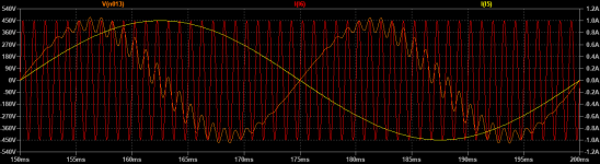
jneutron, is this the eddy current variable damping you were talking about?
Yellow trace is the voicecoil current.
Red trace is voicecoil motion.
Orange trace is the magnetic force opposing the motion of the coil.
I'm trying to understand the waveforms. You added hf and LF, the orange is drag on vc due to LF position?
Jn
You showed simultaneous, no?yes, it is pretty easy to have both V and I fb in an amp. I showed both already. Can easily add a filtering network to the I signal to affect any band or range of freqs to be fed back.
I was thinking about how to get around the hf resistance losses, and am looking for the experts opinions as to if it is possible.
Jn
The one and only one speaker I have scrutinized started to show what I suspect to be Lenz based dissipation effects at around 2kHz. Below that, I would think V control would be adequate. I could see drivers ranging in breakpoint, but don't have a clue yet. I have not seen any papers or analysis on the break over point where shorting rings traverse the "don't care"region to the phase shift flux bucking dissipate region. My only experience is with infinite conductivity rings, so only DC.Yes, I believe so. I think you would have to specify what sort of
transition you would put up with.
If my testing and analysis bears fruit, it may yet be found that a composite FB amp produces better sound, a hybrid of sorts. Perhaps worthy of a paper by somebody here.
It would be great if my ramblings here advance knowledge. If not, so be it..
As I told a friend at dinner at a place where the food was so-so...it's not the food, it's the company..
Cheers, Jn
Edit: to the mods.. At some point in time, would the driver testing and analysis be worth making a sticky? This thread quickly buries pertinent information.
The red trace is coil velocity. The orange trace is the force of the eddy current opposing it in the direction of travel. The coil is electrically driven with 20Hz and is mechanically vibrated at 1KHz. The eddy current force opposes the 1KHz vibration which shows mechanical resistance. The 40Hz wave in the eddy force is a result of the coil current changing polarity and thus the polarity of the flux acting on the eddy current to produce force. If the eddy current weren't phase shifted 90 degrees then this would have a DC component. Eddy currents have a phase between 0 and 90 degrees so in all likelihood there is a small DC component in a real system. Either that or I have yet again failed.
KSTR has already designed an amp that changes drive impedance between bass and treble. We talked about it a while back.
KSTR has already designed an amp that changes drive impedance between bass and treble. We talked about it a while back.
Funny. I made the 2 inch expanding mandrel with the idea of mechanically driving at LF while electrically driving 1kHz....and using tap coil to monitor flux communication looking for dragging. I will make a 2.025 ID dual coil and slide it over my 2 inch dia aluminum stock.
KSTR flips from V drive to I drive midband? How did it measure?
Jn
KSTR flips from V drive to I drive midband? How did it measure?
Jn
You showed simultaneous, no?
I was thinking about how to get around the hf resistance losses, and am looking for the experts opinions as to if it is possible.
Jn
yes. as i said , it can be reworked with suitable filtering as you need for crossing over to I.
However, what is your reason to be Volt drive at low freqs?
??
Anyway, dont we want to improve just the driver without amplifier tricks?
-RNM
Last edited:
Compression in V drive is stable. In I drive, I (being an in-the-field speaker abuser) need to be protected from myself who typically turns the volume to 11.
If simple amp mods can tame existing speaker design issues, why not? You keep asking how to make the perfect driver..working on both is viable.
Jn
If simple amp mods can tame existing speaker design issues, why not? You keep asking how to make the perfect driver..working on both is viable.
Jn
- Status
- Not open for further replies.
- Home
- Member Areas
- The Lounge
- John Curl's Blowtorch preamplifier part III