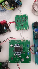
Hello all i need some help. i tried to connect the d3 in simultaneous mode and i´m getting no sound. Connect the MCK from fifopi to WS on i2stosim, SCK to BCK, DATA to DATA.
I am using crystek 22.5792 MHz on FIFOPI. is the clock wrong???
any ideas?
I am using crystek 22.5792 MHz on FIFOPI. is the clock wrong???
any ideas?
Hello all i need some help. i tried to connect the d3 in simultaneous mode and i´m getting no sound. Connect the MCK from fifopi to WS on i2stosim, SCK to BCK, DATA to DATA.
I am using crystek 22.5792 MHz on FIFOPI. is the clock wrong???
any ideas?
Did you change the data input selection on the d3 pcb? You need to put a solder blob on J2.
Did you change the data input selection on the d3 pcb? You need to put a solder blob on J2.
yes now i connected instead of the mck from the fifopi to ws on i2stosim, lrck to ws and it sings.....is playing...
After carefully listen i detect the sound was not so louder and something was missing. i only have the right channel sound playing mono on both speakers... so something wrong is going on here... any ideas??
Hi Ryan,
Will you let me know when the D3 & i2s2sim boards ship?
Will there be any tracking information?
Will you let me know when the D3 & i2s2sim boards ship?
Will there be any tracking information?
After carefully listen i detect the sound was not so louder and something was missing. i only have the right channel sound playing mono on both speakers... so something wrong is going on here... any ideas??
Some thoughts:
Did you remove the solder from J1? Check again.
Double check all soldering on I2S to Simultaneous board.
Double check all soldering on D3 input circuitry.
Play a piece that has recognizable left and right channel information and check the following:
Check your output board. Right input only - what happens? Left input only? Switch inputs?
D3 input - remove Data R - what happens?
D3 input - remove Data L - what happens?
D3 input - switch Data R and Data L -what happens?
The object here is to narrow down the possible locations that may be causing the problem.
Hi Ryan,
Will you let me know when the D3 & i2s2sim boards ship?
Will there be any tracking information?
Yes I sent your PCBs on the 6th. Sorry no tracking info - you didn't check that box.
Yes I sent your PCBs on the 6th. Sorry no tracking info - you didn't check that box.
Ahh, thanks.
My memory is short but bad 😉
I have about 100 hours on my D3 now and I must say, it has gotten better and better. The sound is open with really good high end - extended but not sharp or grating. The realism factor is high. With burn-in, the improvement over my own old diy board is very obvious and noticeable.
Thank you, Ryan.
Thank you, Ryan.
Reading all these reports I can’t wait to get my D3 going. I have it soldered but have yet to finalise the psu- initially I will use the SRPP output from my current setup but have others to try as well. The part I had difficulty with were the medium and large capacitors - they are on the board but I’m not completely happy that they have full contact the whole pad. Will have another go. Not going to get to it real soon as school term has just started and I’m preparing an after school activity to make the “Altoid tin cmoy” head amp with whoever signs up for the fun.
I have about 100 hours on my D3 now and I must say, it has gotten better and better. The sound is open with really good high end - extended but not sharp or grating. The realism factor is high. With burn-in, the improvement over my own old diy board is very obvious and noticeable.
Thank you, Ryan.
Awesome, great result!
Reading all these reports I can’t wait to get my D3 going. I have it soldered but have yet to finalise the psu- initially I will use the SRPP output from my current setup but have others to try as well. The part I had difficulty with were the medium and large capacitors - they are on the board but I’m not completely happy that they have full contact the whole pad. Will have another go. Not going to get to it real soon as school term has just started and I’m preparing an after school activity to make the “Altoid tin cmoy” head amp with whoever signs up for the fun.
The SMD caps can be a challenge at times. I've found that if I tin the pads and the legs then remove the excess solder it flows much better when soldered. I've used solder paste as well in the past and seems to work nicely. Heating the area with some hot air also helps. If you put your finger on the cap while soldering and you can feel it getting hot quickly - chances are it has soldered ok.
Yes flowing the pads helps. The other thing is using a small wet cotton ear bud to hold the smd part in place while soldering. Helps to take heat away from killing the parts.
Cheers
Cheers
Can anyone recommend a reliable source for the TDA1541A chip?
https://rover.ebay.com/rover/0/0/0?mpre=https://www.ebay.com/p/1623860153
Those are non-A chips - not equivalent to TDA1541A.
So you want an inferior chip?
- Home
- Group Buys
- DIY TDA1541A PCB "D3"
