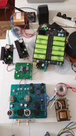
Boards arrived safely in Mississippi yesterday.
Thanks Ryan!
Now I need to catch up on what's the latest in the I2S conversion boards.
Greg in Mississippi
Hi Greg,
Your welcome. If you need a converter board let me know.
Edit : i see you already got a couple a while back. 🙂
Last edited:
Hello i bought the bom for tda1541a d3 and the i2sim board...tomorrow i will heat the iron.. 🙂
Now what board should i use for i2s? I have ians fifopi, i2soverusb viii, hifiberry dac pro and digi pro....
What are you using? I'm asking because they sound diferent lol... they should not..
Now what board should i use for i2s? I have ians fifopi, i2soverusb viii, hifiberry dac pro and digi pro....
What are you using? I'm asking because they sound diferent lol... they should not..
I know this thread about D3 distinction but when i was waiting for the components i decided to put the D2 version to work and since i had ians fifo pi at work i decided try in i2s mode since my d2 board was configured for i2s and i m using a valve output that i bough some time ago...
The sound is very good. Very clean and real sensation..
Now it will be nice to compare to d3 with simultaneous mode.
The sound is very good. Very clean and real sensation..
Now it will be nice to compare to d3 with simultaneous mode.

I received my boards a couple days ago. Now to get them built.
I'd still be interested in finding a way to run as dual/mono.
I'd still be interested in finding a way to run as dual/mono.
I know this thread about D3 distinction but when i was waiting for the components i decided to put the D2 version to work and since i had ians fifo pi at work i decided try in i2s mode since my d2 board was configured for i2s and i m using a valve output that i bough some time ago...
The sound is very good. Very clean and real sensation..
Now it will be nice to compare to d3 with simultaneous mode.View attachment 773289
It will be interesting to hear your comparison.
I received my boards a couple days ago. Now to get them built.
I'd still be interested in finding a way to run as dual/mono.
xaled made a converter PCB that can support dual mono if I recall correctly, maybe contact him.
Thank you for all you have done. The boards arrived safely.
You're welcome. Enjoy!
Hi Ryan,
Boards have arrived. They look really nice, hope the sound will be similar!
Some hints how to make it live after assembling?
The floating 26V has to be prestabilized, or a simple filtering is enough?
regards, Gábor
Boards have arrived. They look really nice, hope the sound will be similar!
Some hints how to make it live after assembling?
The floating 26V has to be prestabilized, or a simple filtering is enough?
regards, Gábor
Hi Ryan,
Boards have arrived. They look really nice, hope the sound will be similar!
Some hints how to make it live after assembling?
The floating 26V has to be prestabilized, or a simple filtering is enough?
regards, Gábor
Hi Garbor,
Glad they arrived ok. The 26V supply doesn't have to be very well regulated, but a good amount of filtering is welcome. Aim between 26 and 27 volts and you should be fine. I've run mine up to 28V although I was using a heat sink on the CCS as can be seen in one of the pictures I uploaded on post #78.
Hello Friends 🙂 i just finished my D3 board. It took yesterday almost all day to soldering. Some very small components were a challenge and pain to solder because tip tip of my iron is to big i checked everything on magnifying glass. I connect exactly the same way as d2 (i2s mode) just to compare because i don t have yet the i2stosim done.
It is working and i m happy and i like the sound even more . Very fluid 🙂 full of details.
Just need some help with the 2 trimpots. Do i measure dc on the output between signal and ground and ajust each one to 0v? With music playing? With the output stage connected?

It is working and i m happy and i like the sound even more . Very fluid 🙂 full of details.
Just need some help with the 2 trimpots. Do i measure dc on the output between signal and ground and ajust each one to 0v? With music playing? With the output stage connected?


Hello Friends 🙂 i just finished my D3 board. It took yesterday almost all day to soldering. Some very small components were a challenge and pain to solder because tip tip of my iron is to big i checked everything on magnifying glass. I connect exactly the same way as d2 (i2s mode) just to compare because i don t have yet the i2stosim done.
It is working and i m happy and i like the sound even more . Very fluid 🙂 full of details.
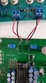
Just need some help with the 2 trimpots. Do i measure dc on the output between signal and ground and ajust each one to 0v? With music playing? With the output stage connected?View attachment 773998View attachment 773999
Nice work!
Yes, just measure across the outputs. You can zero the DC on AOL and AOR while playing music.
Ok thanks for the help.. during playing music but connected to output stage or unconnected?Nice work!
Yes, just measure across the outputs. You can zero the DC on AOL and AOR while playing music.
I am soldering the i2stosim now... i hope today a can connect it.
Good work! It's tough to solder those small regulators with a iron.
From your picture, it looks like the IV resistor for each channel is at the input of the output stage. You should be able to measure the DC across the resistor by placing the probes on the input, with the D3 connected to it. The output stage does not need to be powered up. The D3 does not need to be playing music, but it will also work if it is playing.
The TDA1541A outputs 2mA of current constantly which is converted to a DC voltage across the IV resistor. Adjusting the pot will null this DC voltage.
There is one thing to consider. Is your output stage designed to take advantage of the 2mA constant output of the TDA1541A? Some designers of tube output stages for TDA1541A use this bias to help bias the tube. If it is , then the nulling circuit should be disabled. That can be done by removing R32 and R33. If your output stage was not designed specifically for the TDA1541A, then null the offset.
There is a note on Ryan's schematic named "Bias" that refers to the output stage.
By the way, it looks like you have the left output from the D3 connected to the right input of your output stage.
Good work! It's tough to solder those small regulators with a iron.
From your picture, it looks like the IV resistor for each channel is at the input of the output stage. You should be able to measure the DC across the resistor by placing the probes on the input, with the D3 connected to it. The output stage does not need to be powered up. The D3 does not need to be playing music, but it will also work if it is playing.
The TDA1541A outputs 2mA of current constantly which is converted to a DC voltage across the IV resistor. Adjusting the pot will null this DC voltage.
There is one thing to consider. Is your output stage designed to take advantage of the 2mA constant output of the TDA1541A? Some designers of tube output stages for TDA1541A use this bias to help bias the tube. If it is , then the nulling circuit should be disabled. That can be done by removing R32 and R33. If your output stage was not designed specifically for the TDA1541A, then null the offset.
There is a note on Ryan's schematic named "Bias" that refers to the output stage.
By the way, it looks like you have the left output from the D3 connected to the right input of your output stage.
Hello Ben Mah, thanks for the help. This output stage was designed specific for the tda1541a.. i think then i must disable the null system. I have something happening here on d3 when i put volume up (digital volume on computer) the sound get garbled a bit distort.. at low volume is super clean...i checked the voltages on the tda pins -15, -5 +5 and they are ok.
On the d2 this does not happen...maybe because does not have null system...
Yes i have the channels swaped! Thanks.
- Home
- Group Buys
- DIY TDA1541A PCB "D3"
