Has anyone assembled the board and have it running?
Ryan,
I have run into problems and I am stuck.
I put mine together and when I powered it up, the voltages were off a bit and also jumping around so I reheated the solder joints. It ended up making it even worse - the voltages became steady but quite a bit low. I checked for the 2.5V reference on the TL431 and it was not there. So I removed all three TL431 and put a new one back at the -15V position. I was able to measure Vref=2.5V and the output voltage was -10.0V.
Looking at the PS schematic, I see that the resistors at the TL431 are R27+R29=3010R, and R30=1K. Doing Vout calculation, Vout= (3010R/1000R+1)x2.5V=10.0V. I don't know whether this result is a coincidence or it is because there are other components that are still damaged.
I then put a new TL431 into the -5V supply. Result was no voltage out. Looking at the schematic, it looks like the Ground for the -15V supply is connected to the -5V input.
I am confused - I am probably missing a lot as far as understanding how the -5V and -15V supplies work. 😕
My problems are probably due to damaged parts, and I need to figure out what's damaged.
Well, it is late morning now and I need to sleep. I pulled an all-nighter trying to get this working.
Has anyone assembled the board and have it running?
Ryan,
I have run into problems and I am stuck.
I put mine together and when I powered it up, the voltages were off a bit and also jumping around so I reheated the solder joints. It ended up making it even worse - the voltages became steady but quite a bit low. I checked for the 2.5V reference on the TL431 and it was not there. So I removed all three TL431 and put a new one back at the -15V position. I was able to measure Vref=2.5V and the output voltage was -10.0V.
Looking at the PS schematic, I see that the resistors at the TL431 are R27+R29=3010R, and R30=1K. Doing Vout calculation, Vout= (3010R/1000R+1)x2.5V=10.0V. I don't know whether this result is a coincidence or it is because there are other components that are still damaged.
I then put a new TL431 into the -5V supply. Result was no voltage out. Looking at the schematic, it looks like the Ground for the -15V supply is connected to the -5V input.
I am confused - I am probably missing a lot as far as understanding how the -5V and -15V supplies work. 😕
My problems are probably due to damaged parts, and I need to figure out what's damaged.
Well, it is late morning now and I need to sleep. I pulled an all-nighter trying to get this working.
If you had damage, check all the grounds. Maybe a blown ground trace?
The BOM and schematics are on posts #91 and #92 respectively.
After a few hours of sleep, it looks to me that the -5V supply and the -10V stack to provide -5V and -15V.
I will check some more based on this.
After a few hours of sleep, it looks to me that the -5V supply and the -10V stack to provide -5V and -15V.
I will check some more based on this.
The BOM and schematics are on posts #91 and #92 respectively.
After a few hours of sleep, it looks to me that the -5V supply and the -10V stack to provide -5V and -15V.
I will check some more based on this.
Thank you!
Good news - finally found the short. It was at Q3. I replaced Q3 and during removal and replacement I managed to damage the solder mask and created a short. It's fixed now and I have -15V and -5V.
I am now going to get the 5V working and hopefully it will be done soon.
I am now going to get the 5V working and hopefully it will be done soon.
After a couple more bad solder joints, including one at the left digital input, it's playing with a sacrificial/testing TDA1541 non-A chip.
Next will be installing my S1 A chip.
What a relief!!
Next will be installing my S1 A chip.
What a relief!!
After a couple more bad solder joints, including one at the left digital input, it's playing with a sacrificial/testing TDA1541 non-A chip.
Next will be installing my S1 A chip.
What a relief!!
Good work Ben! Not always easy tracking down bad solder joints and damaged parts. Once I desoldered a whole PSU section of a board to track down a short. Turned out to be the 470uF cap on the -15V that was shorted.
Has anyone assembled the board and have it running?
Ryan,
I have run into problems and I am stuck.
I put mine together and when I powered it up, the voltages were off a bit and also jumping around so I reheated the solder joints. It ended up making it even worse - the voltages became steady but quite a bit low. I checked for the 2.5V reference on the TL431 and it was not there. So I removed all three TL431 and put a new one back at the -15V position. I was able to measure Vref=2.5V and the output voltage was -10.0V.
Looking at the PS schematic, I see that the resistors at the TL431 are R27+R29=3010R, and R30=1K. Doing Vout calculation, Vout= (3010R/1000R+1)x2.5V=10.0V. I don't know whether this result is a coincidence or it is because there are other components that are still damaged.
I then put a new TL431 into the -5V supply. Result was no voltage out. Looking at the schematic, it looks like the Ground for the -15V supply is connected to the -5V input.
I am confused - I am probably missing a lot as far as understanding how the -5V and -15V supplies work. 😕
My problems are probably due to damaged parts, and I need to figure out what's damaged.
Well, it is late morning now and I need to sleep. I pulled an all-nighter trying to get this working.
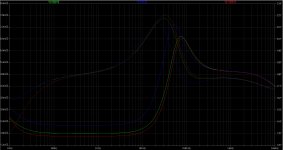
The -5 and -15 supplies are actually a -5 and -10 stacked in series to get the required voltage of -15. I know its kind of odd and unconventional, but it works really well. Its also simulates really well. Basically the whole PSU is working in parallel with the 1541 and providing a very low output impedance in the audio range of around 2mΩ.
Ill attach the simulation.
Attachments
Hi Ryan,
It's running with the S1 chip now and it sounds very good.
It is a small but significant improvement over my diy copper foil and Veroboard setup. I was quite happy with my old setup even though it started out many years ago, before Ian's fifo and clocks and Lucien's WaveIO. When I first built my board, it had on-board flip-flops for reclocking and a clock divider for the original dem reclocking. USB to I2S was a DDAC board. It had been slowly updated with Ian's Fifo and clocks, and WaveIO, and then further with Ian's and then your simultaneous boards, and also Ian's Pi/I2S board.
I am noticing further sound stage depth and width and I think a bit more bass with your board. However, it is difficult to put into words. I do know that it sounds better. As I mentioned earlier, the changes are small but significant.
The build was certainly challenging, made so because of my soldering. I used hot air for the smaller components and a soldering iron for the bigger pieces. I found that the cylindrical resistors and diodes were the most challenging as too much air or motion would sent them rolling. Also with the electrolytics, it took forever to get to temperature. The components with heat sinks took a long time too. I ended up soldering them with an iron.
Usually when I build a project, I would build and test in stages. However with smd parts and a small board, I didn't want to build and test in stages because I didn't want to heat the board too many times with hot air. So I soldered it all before testing. I attempted to check my solder joints with my meter but it seemed that I was not too successful.
With the board fully populated, trouble shooting was definitely challenging. A bit of Ohm's Law and some understanding of electrical circuits was definitely useful. Fortunately for me I had built my own board previously so I was able to put that experience and knowledge to use.
So thank you, Ryan for designing the Distinction D3 and making it available to diyers. 😀
The high frequencies seem more extended too. Everything seems a bit more defined. It's getting better and better.
By the way, I was already running 50Hz dem on my own diy board. I/V is passive with hand wound 65R resistors, carried over from my old board.
By the way, I was already running 50Hz dem on my own diy board. I/V is passive with hand wound 65R resistors, carried over from my old board.
Hi Ryan,
It's running with the S1 chip now and it sounds very good.
It is a small but significant improvement over my diy copper foil and Veroboard setup. I was quite happy with my old setup even though it started out many years ago, before Ian's fifo and clocks and Lucien's WaveIO. When I first built my board, it had on-board flip-flops for reclocking and a clock divider for the original dem reclocking. USB to I2S was a DDAC board. It had been slowly updated with Ian's Fifo and clocks, and WaveIO, and then further with Ian's and then your simultaneous boards, and also Ian's Pi/I2S board.
I am noticing further sound stage depth and width and I think a bit more bass with your board. However, it is difficult to put into words. I do know that it sounds better. As I mentioned earlier, the changes are small but significant.
The build was certainly challenging, made so because of my soldering. I used hot air for the smaller components and a soldering iron for the bigger pieces. I found that the cylindrical resistors and diodes were the most challenging as too much air or motion would sent them rolling. Also with the electrolytics, it took forever to get to temperature. The components with heat sinks took a long time too. I ended up soldering them with an iron.
Usually when I build a project, I would build and test in stages. However with smd parts and a small board, I didn't want to build and test in stages because I didn't want to heat the board too many times with hot air. So I soldered it all before testing. I attempted to check my solder joints with my meter but it seemed that I was not too successful.
With the board fully populated, trouble shooting was definitely challenging. A bit of Ohm's Law and some understanding of electrical circuits was definitely useful. Fortunately for me I had built my own board previously so I was able to put that experience and knowledge to use.
So thank you, Ryan for designing the Distinction D3 and making it available to diyers. 😀
Thanks for sharing that Ben, and your very welcome - makes it all worth it when diyers like yourself get a good result.
Just on the topic of soldering for everyone that is going to build this PCB - do yourself a favor and use a good quality flux, particularly for the SOT-23 and 0603 packages. A great one is Amtech NC-559-V2-TF Tacky Flux, beware of fakes, this one is only made in the USA.
One other thing I use is a clip on microscope lens for my phone to inspect my solder joints, which has been very helpful:
60X-Zoom-Microscope-Clip-Magnifier-Camera-LED-Micro-Lens-For-All-Cell-Phone
Thanks for sharing that Ben, and your very welcome - makes it all worth it when diyers like yourself get a good result.
Just on the topic of soldering for everyone that is going to build this PCB - do yourself a favor and use a good quality flux, particularly for the SOT-23 and 0603 packages. A great one is Amtech NC-559-V2-TF Tacky Flux, beware of fakes, this one is only made in the USA.
[/URL]
Where do you source that in Aus Ryan? 🙂
Where do you source that in Aus Ryan? 🙂
Not sure, I got it from the USA. Alternatively try some cheap flux from China.
All Amtech NC-559 from China are fakes. And I would be cautions about any source outside the USA.
@Ben
For piece of mind, get a digital thermometer with probes.
Check how close to set hot air temperature you are.
I also have a laser pointing IR temp-gun that I check the PCB temp with.
And if you want to do more SMD's in the future, get either a preheating station to go with your hot air or get/build a reflow oven. That is assuming you are using solder paste.
If you are, avoid the cheapest stuff as it tends to leave solder balls all over your board.
About the hot air, keeping flow low and going over melf/minimelf etc from straight above keep them in place better.
Not sure, I got it from the USA. Alternatively try some cheap flux from China.
All Amtech NC-559 from China are fakes. And I would be cautions about any source outside the USA.
Got some "Amtech" off ebay long ago, used it once...
It gave off the worst fish smell you can imagine when you applied heat.
I built the VHEX last year and it had tons of very small SMDs, I just used my head loop with strong power objective. I hit each pad with a flux pen, just dabbing the pad. Worked great and it was my first ever serious SMD build. Both amp boards powered up and worked flawlessly. It was a LOT of SMDs!
@Ben
For piece of mind, get a digital thermometer with probes.
Check how close to set hot air temperature you are.
I also have a laser pointing IR temp-gun that I check the PCB temp with.
And if you want to do more SMD's in the future, get either a preheating station to go with your hot air or get/build a reflow oven. That is assuming you are using solder paste.
If you are, avoid the cheapest stuff as it tends to leave solder balls all over your board.
About the hot air, keeping flow low and going over melf/minimelf etc from straight above keep them in place better.
A digital thermometer would have been useful - no need then to guess the board temperature versus the stated air temperature.
A preheating station would have helped since the board has multiple layers and took a while to heat up. For this board and components, an oven would probably be the best. Diyers have successfully rigged toaster ovens for soldering.
I do very few smd projects and this was the biggest and most difficult to date. It will probably be quite a while before I do another one. This dac will be good for a long time.
There's a ton of videos on youtube (often with links to arduino code) on diy reflow ovens.
It's on my to-do list.
That list, btw, should keep me occupied the next decade or so lol
- Home
- Group Buys
- DIY TDA1541A PCB "D3"